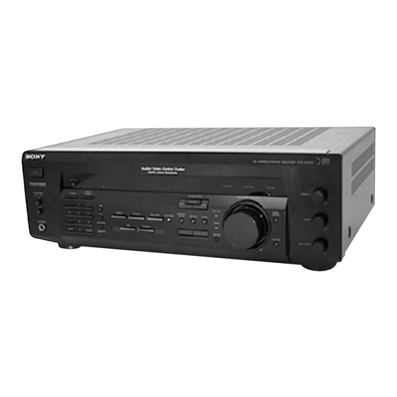
Sony STR-DE335 Service Manual
Hide thumbs
Also See for STR-DE335:
- Operating instructions manual (136 pages) ,
- Service manual (45 pages) ,
- Limited warranty (1 page)
Table of Contents
Advertisement
STR-DE335/SE391/V323
SERVICE MANUAL
Audio power specifications (US model)
POWER OUTPUT AND TOTAL HAR-
MONIC DISTORTION
With 8-ohm load, both channels driven,
from 20
a)
– 20,000 Hz, rated 100 watts
per channel minimum RMS power, with
no more than 0.09 %
b)
total harmonic
distortion from 250 milliwatts to rated
output.
STR-SE391:
a) 40Hz
b) 0.5 %
Amplifier section
Power output
Stereo mode
STR-DE335/V323
US, Canadian models:
(8 ohms at 20 Hz – 20 kHz
less than 0.09 % total
harmonic distortion)
100 W + 100 W
AEP model:
(DIN 1 kHz, 4 ohms)
80 W + 80 W
Malaysia, Singapore,
Chinese, Australian
models:
Rated power:
(8 ohms at 1 kHz,
THD 0.7 %)
80 W + 80 W
Reference power:
(8 ohms at 20 Hz – 20 kHz,
less than 0.09 % total
harmonic distortion)
70 W + 70 W
E model:
Rated power: (8 ohms at
1kHz, THD 0.7 %)
100 W + 100 W
MICROFILM
Photo: STR-DE335 US model
SPECIFICATIONS
Reference power:
(8 ohms at 20 Hz – 20 kHz,
less than 0.09 % total
harmonic distortion)
95 W + 95 W
STR-SE391
(8 ohms at 40 Hz – 20 kHz,
less than 0.5 % total
harmonic distortion)
100 W + 100 W
Surround mode
STR-DE335/V323
and 5.1 CH/DVD US, Canadian models:
mode
(8 ohms at 1 kHz, THD
(Reference)
0.8%)
Front: 80 W/ch
Center: (Pro Logic mode)
80 W
Rear: 80 W/ch
AEP model:
(DIN 1 kHz, 4 ohms)
Front: 70 W/ch
Center: 70 W
(only in PRO LOGIC
mode)
Rear: 70 W/ch
E, Malaysia, Singapore,
Chinese, Australian
models:
Rated power: (8 ohms at
1 kHz, THD 0.7 %)
Front: 80 W/ch
Center: (Pro Logic mode)
80 W
Rear: 80 W/ch
FM STEREO/FM-AM RECEIVER
US Model
STR-DE335/SE391
Canadian Model
AEP Model
E Model
Australian Model
STR-DE335
Chinese Model
STR-SE391
(8 ohms at 1 kHz,
THD 0.5 %)
Front: 80 W/ch
Center: (Pro Logic mode)
80 W
Rear: 80 W/ch
Reference power:
(8 ohms 20 Hz – 20 kHz,
less than 0.09 % total
harmonic distortion)
Front: 70 W/ch
Center: (Pro Logic mode)
70 W
Rear: 70 W/ch
RMS power:
(8 ohms at 1 kHz,
THD 10 %)
Front: 100 W/ch
Center: (Pro Logic mode)
100 W
Rear: 100 W/ch
Frequency
PHONO: RIAA
response
equalization curve ±0.5 dB
(STR-SE391)
TV/SAT (TV/LD), CD,
MD/TAPE, VIDEO
5.1 CH/DVD:
10 Hz – 50 kHz ± 1 dB
– Continued on next page –
STR-V323
Advertisement
Table of Contents

Summary of Contents for Sony STR-DE335
- Page 1 Canadian Model AEP Model E Model Australian Model STR-DE335 Chinese Model STR-V323 Photo: STR-DE335 US model SPECIFICATIONS Audio power specifications (US model) Reference power: STR-SE391 (8 ohms at 20 Hz – 20 kHz, (8 ohms at 1 kHz, POWER OUTPUT AND TOTAL HAR- less than 0.09 % total...
- Page 2 VIDEO FCR-IN (Page 11) MUTE MUTING VIDEO OUT TV/LD Q363 FCLS-IN VIDEO IN S-RCH LINE AMP REAR RS-OUT IC502 STR-DE335: AEP, E, Malaysia, –2 FCRS-IN (Page 11) Singapore/STR-V323 MUTING Q364 CENTER J252 (1/2) IC MUTE LC-INB VIDEO RV421 RV422 RV423...
- Page 3 BASS BOOST BASS BOOST FILTER AMP SWITCH SPEAKERS FRONT Q452 Q401 IMPEDANCE USE 8 – 16Ω POWER AMP – S701–2–2 IC702 (1/2) (EXCEPT STR-DE335: AEP) S701–3–1 +VOUT1 –2 FINAL SPEAKERS FRONT DRIVER DRIVER –VOUT1 DRIVE IMPEDANCE (Page 10) BIAS Q753, 754 USE 4 –...
-
Page 4: Block Diagram - Display/Power Supply Section
CNJ903 S221, 228, 245: STR-SE391, FLUORESCENT IC803 POWER S231: STR-DE335: AEP INDICATOR RDS DECODER: AC OUTLET TRANSFORMER TUBE STR-DE335 AEP model only. SWITCHED 100W MAX +12V FL201 (VIDEO AMP: STR-DE335/V323 only.) +12V REGULATOR RECT IC801 D820 – 823 REMOTE CONTROL... -
Page 5: Schematic Diagram - Main Board (1/4)/Rear Amp Board
STR-DE335/SE391/V323 5-7. SCHEMATIC DIAGRAM – MAIN Board (1/4)/REAR AMP Board – • See page 42 for IC Block Diagrams. (Page 39) (Page 39) (Page (Page 27) (Page 40) The components identified by Les composants identifiés par une mark ! or dotted line with marque ! sont critiques pour la mark ! are critical for safety. -
Page 6: Schematic Diagram - Main Board (2/4)/Sp Sw Board
STR-DE335/SE391/V323 5-8. SCHEMATIC DIAGRAM – MAIN Board (2/4)/SP SW Board – (Page 26) (Page 31) The components identified by Les composants identifiés par une mark ! or dotted line with marque ! sont critiques pour la mark ! are critical for safety. -
Page 7: Schematic Diagram - Main Board
STR-DE335/SE391/V323 5-9. SCHEMATIC DIAGRAM – MAIN Board (3/4) – • See page 18 for Waveforms. • See page 41 for IC Block Diagrams. (Page 26) (Page 39) (Page 31) (Page 39) (Page 35) – 29 – – 30 –... -
Page 8: Schematic Diagram - Main Board (4/4)/Secondary Board/Standby Board/Primary Board/Vol Sel Board
STR-DE335/SE391/V323 5-10. SCHEMATIC DIAGRAM – MAIN Board (4/4)/SECONDARY Board/STANDBY Board/PRIMARY Board/VOL SEL Board – • See page 43 for IC Block Diagram. (Page 27) (Page 30) The components identified by Les composants identifiés par une mark ! or dotted line with marque ! sont critiques pour la mark ! are critical for safety. -
Page 9: Schematic Diagram - Panel Section
STR-DE335/SE391/V323 5-12. SCHEMATIC DIAGRAM – PANEL Section – • • See page 18 for Waveform. See page 43 for IC Block Diagram. EXCEPT DE335: MY,SP,AUS/ V323 (Page 29) EXCEPT DE335: MY,SP,AUS/ V323 (Page 39) The components identified by Les composants identifiés par une... -
Page 10: Schematic Diagram - Volume Board/Tone Board/Video Board/Phono Board
STR-DE335/SE391/V323 5-14. SCHEMATIC DIAGRAM – VOLUME Board/TONE Board/VIDEO Board/PHONO Board – • See page 43 for IC Block Diagram. (Page 35) (Page 25) (Page 25) (Page 25) (Page 29) (Page 29) (Page 25) The components identified by Les composants identifiés par une...


