HP t310 Hardware Reference Manual
Zero client
Hide thumbs
Also See for t310:
- Datasheet (4 pages) ,
- Disassembly instructions manual (6 pages) ,
- Disassembly instructions (2 pages)
Table of Contents
Advertisement
Quick Links
Advertisement
Table of Contents

Summary of Contents for HP t310
- Page 1 HP t310 Zero Client Hardware Reference Guide...
- Page 2 Nothing herein should be construed as constituting an additional warranty. HP shall not be liable for technical or editorial errors or omissions contained herein. This document contains proprietary information that is protected by copyright.
- Page 3 About This Book WARNING! Text set off in this manner indicates that failure to follow directions could result in bodily harm or loss of life. CAUTION: Text set off in this manner indicates that failure to follow directions could result in damage to equipment or loss of information.
- Page 4 About This Book...
-
Page 5: Table Of Contents
Table of contents 1 Front and Top Panel Components ..................1 2 Rear and Bottom Panel Components ................. 2 Appendix A Thin Client Operation ..................3 Routine Thin Client Care ......................3 Supported Orientations ......................4 Non-supported Orientation ......................6 Appendix B Electrostatic Discharge .................. -
Page 7: Front And Top Panel Components
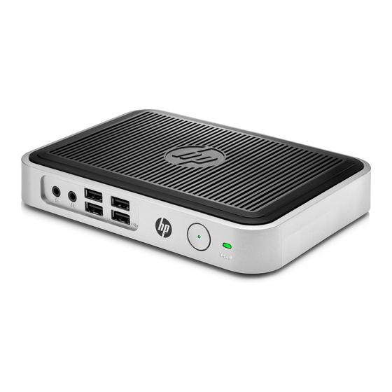
Front and Top Panel Components For more information, go to www.hp.com/go/productbulletin and search for your specific thin client model to find the model-specific QuickSpecs. Figure 1-1 Front and top panel components Line-in (microphone) connector Power LED Line-out (headphone) audio connector... -
Page 8: Rear And Bottom Panel Components
Rear and Bottom Panel Components For more information, go to www.hp.com/go/productbulletin and search for your specific thin client model to find the model-specific QuickSpecs. Figure 2-1 Rear panel components Serial number location Cable lock slot Rubber feet Power connector Universal serial bus (USB) connectors (2) -
Page 9: Appendix A Thin Client Operation
Thin Client Operation Routine Thin Client Care Use the following information to properly care for your thin client: Never operate the thin client with the outside panel removed. ● Keep the thin client away from excessive moisture, direct sunlight, and extreme heat and cold. ●... -
Page 10: Supported Orientations
Supported Orientations HP supports the following orientations for the thin client. CAUTION: You must adhere to HP-supported orientations to ensure your thin clients function properly. Figure A-1 Horizontal orientation on rubber feet Figure A-2 Vertical orientation Appendix A Thin Client Operation... - Page 11 Figure A-3 Under monitor stand with at least one inch clearance Supported Orientations...
-
Page 12: Non-Supported Orientation
Non-supported Orientation HP does not support the following orientation for the thin client. CAUTION: Non-supported placement of thin clients could result in operation failure and/or damage to the devices. CAUTION: Thin clients require proper ventilation to maintain operating temperature. Do not block the vents. -
Page 13: Appendix B Electrostatic Discharge
● Use a portable field service kit with a folding static-dissipating work mat. ● If you do not have any of the suggested equipment for proper grounding, contact an HP authorized dealer, reseller, or service provider. NOTE: For more information about static electricity, contact an HP authorized dealer, reseller, or service provider. -
Page 14: Appendix C Shipping Information
Find support telephone numbers ● Locate an HP service center ● In all cases, remove and safeguard all external options before returning the thin client to HP for exchange. NOTE: The external power supply need not be returned. Appendix C Shipping Information... -
Page 15: Index
Index bottom panel components 2 serial number location 2 service repair 8 shipping preparation 8 cautions speaker connector location 2 thin client orientation 4, 6 supported orientations 4 ventilation 6 horizontal 4 under monitor stand 4 DVI-D connector location 2 DVI-I connector location 2 top panel components 1 electrostatic discharge 7...


