Sign In
Upload
Manuals
Brands
Epson Manuals
Robotics
LS-B Series
Epson LS-B Series Manuals
Manuals and User Guides for Epson LS-B Series. We have
3
Epson LS-B Series manuals available for free PDF download: Maintenance Manual, Manual, Safety And Installation
Epson LS-B Series Maintenance Manual (364 pages)
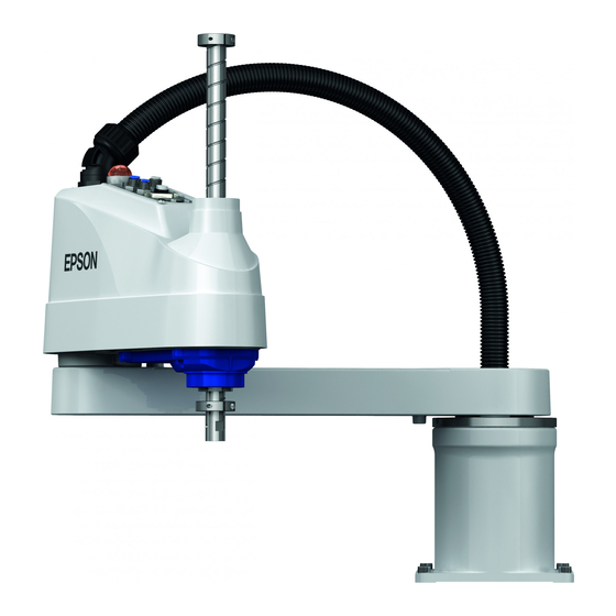
SCARA ROBOT
Brand:
Epson
| Category:
Robotics
| Size: 14.28 MB
Table of Contents
Table of Contents
9
LS3-B, LS6-B Manipulator
15
Safety Maintenance
17
General Maintenance
18
Maintenance Inspection
18
Schedule for Maintenance Inspection
18
Inspection Point
19
Overhaul (Parts Replacement)
20
Greasing
22
Tightening Hexagon Socket Head Cap Bolts
25
Matching Origins
25
Layout of Maintenance Parts
26
Covers
27
Arm Top Cover
28
Arm Bottom Cover
29
Connector Plate
30
Connector Sub Plate
31
User Plate
31
Cable
32
Replacing Cable Unit
33
Wiring Diagrams
39
Signal Cable
39
Power Cable
41
User Cable
42
Color of Cables
42
Replacing M/C Cable
43
Joint #1
48
Replacing Joint #1 Motor
49
Replacing Joint #1 Reduction Gear Unit
53
Joint #2
56
Replacing Joint #2 Motor
57
Replacing Joint #2 Reduction Gear Unit
62
Joint #3
66
Replacing Joint #3 Motor
67
Replacing the Timing Belt
71
Replacing the Brake
75
Checking the Timing Belt Tension (Z Belt)
79
Joint #4
80
Replacing Joint #4 Motor
81
Replacing the Timing Belt
86
U2 Belt
87
U1 Belt
93
Replacing the Brake (for LS6-B Series Only)
97
Checking the Timing Belt Tension (U1, U2 Belts)
100
Bellows
101
Ball Screw Spline Unit Replacement
104
Boards
107
Replacing the Converter Board
108
Replacing the Control Board
110
LED Lamp
111
Calibration
113
About Calibration
113
Calibration Procedure
114
Accurate Calibration of Joint #2
124
Calibration Procedure Without Using Calibration Wizard
126
Maintenance Parts List
130
Ls3-B
130
Ls6-B
131
Safety Maintenance
137
General Maintenance
138
Maintenance Inspection
138
Schedule for Maintenance Inspection
138
Inspection Point
139
Overhaul (Parts Replacement)
140
Greasing
142
Tightening Hexagon Socket Head Cap Bolts
145
Matching Origins
145
Layout of Maintenance Parts
146
Covers
147
Arm Top Cover
148
Arm Bottom Cover
149
Connector Plate
149
Connector Sub Plate
151
User Plate
152
Cable
153
Replacing Cable Unit
154
Wiring Diagrams
159
Signal Cable
159
Power Cable
160
User Cable
161
Color of Cables
161
Replacing M/C Cable
162
Joint #1
167
Replacing Joint #1 Motor
168
Replacing Joint #1 Reduction Gear Unit
172
Joint #2
175
Replacing Joint #2 Motor
176
Replacing Joint #2 Reduction Gear Unit
180
Joint #3
184
Replacing Joint #3 Motor
185
Replacing the Timing Belt
189
Replacing the Brake
193
Checking the Timing Belt Tension (Z Belt)
197
Joint #4
198
Replacing Joint #4 Motor
199
Replacing the Timing Belt
203
U2 Belt
204
U1 Belt
210
Replacing the Brake
214
Checking the Timing Belt Tension (U1, U2 Belts)
217
Bellows
218
Ball Screw Spline Unit Replacement
220
Boards
223
Replacing the Converter Board
224
Replacing the Control Board
226
LED Lamp
227
Calibration
228
About Calibration
228
Calibration Procedure
229
Accurate Calibration of Joint #2
239
Calibration Procedure Without Using Calibration Wizard
241
Maintenance Parts List
245
Safety Maintenance
249
General Maintenance
250
Maintenance Inspection
250
Schedule for Maintenance Inspection
250
Inspection Point
251
Overhaul (Parts Replacement)
252
Greasing
254
Tightening Hexagon Socket Head Cap Bolts
257
Matching Origins
257
Layout of Maintenance Parts
258
Covers
259
Arm Top Cover
260
Arm Bottom Cover
261
Arm #1 Cover
261
Connector Plate
262
Connector Sub Plate
263
User Plate
264
Duct Plate
264
Cable
265
Replacing Cable Unit
266
Wiring Diagrams
272
Signal Cable
272
Power Cable
273
User Cable
274
Color of Cables
275
Replacing M/C Cable
276
Joint #1
281
Replacing Joint #1 Motor
282
Replacing Joint #1 Reduction Gear Unit
286
Joint #2
289
Replacing Joint #2 Motor
290
Replacing Joint #2 Reduction Gear Unit
294
Joint #3
298
Replacing Joint #3 Motor
299
Replacing the Timing Belt
303
Replacing the Brake
309
Checking the Timing Belt Tension (Z Belt)
314
Joint #4
315
Replacing Joint #4 Motor
316
Replacing the Timing Belt
321
Replacing the Brake
326
Replacing the Reduction Gear Unit
332
Checking the Timing Belt Tension (U Belt)
335
Bellows
336
Ball Screw Spline Unit Replacement
338
Boards
341
Replacing the Converter Board
342
Replacing the Control Board
343
LED Lamp
344
Calibration
345
About Calibration
345
Calibration Procedure
346
Accurate Calibration of Joint #2
356
Calibration Procedure Without Using Calibration Wizard
358
Maintenance Parts List
362
Advertisement
Epson LS-B Series Manual (252 pages)
Industrial Robot: SCARA ROBOT
Brand:
Epson
| Category:
Robotics
| Size: 6.83 MB
Table of Contents
Table of Contents
11
LS3-B LS6-B Manipulator
19
Safety
21
Conventions
21
Design and Installation Safety
22
Strength of the Ball Screw Spline
23
Operation Safety
24
Emergency Stop
26
Safeguard
27
Emergency Movement Without Drive Power
28
ACCELS Setting for CP Motions
29
Warning Labels
30
Response for Emergency or Malfunction
32
Collision
32
Getting Body Caught in Manipulator
32
Specifications
33
Model Number
33
Part Names and Outer Dimensions
35
Ls3-B
35
Ls6-B
39
Specifications
43
How to Set the Model
43
Environments and Installation
44
Environmental Conditions
44
Base Table
46
Mounting Dimensions
47
Unpacking and Transportation
48
Installation Procedure
49
Standard-Model
49
Cleanroom-Model
50
Connecting the Cables
51
User Wires and Pneumatic Tubes
52
Relocation and Storage
54
Precautions for Relocation and Storage
54
Relocation
55
Setting of End Effectors
57
Attaching an End Effector
57
Attaching Cameras and Valves
59
Weight and Inertia Settings
60
Weight Setting
60
Inertia Setting
64
Precautions for Auto Acceleration/Deceleration of Joint #3
69
Motion Range
72
Motion Range Setting by Pulse Range
72
Max. Pulse Range of Joint #1
73
Max. Pulse Range of Joint #2
73
Max. Pulse Range of Joint #3
74
Max. Pulse Range of Joint #4
74
Motion Range Setting by Mechanical Stops
75
Setting the Mechanical Stops of Joints #1 and #2
76
Setting the Mechanical Stop of Joint #3
78
Setting the Cartesian (Rectangular) Range in the XY Coordinate System of the Manipulator
79
Standard Motion Range
80
LS10-B Manipulator
85
Safety
87
Conventions
87
Design and Installation Safety
88
Strength of the Ball Screw Spline
89
Operation Safety
90
Emergency Stop
92
Safeguard
93
Emergency Movement Without Drive Power
94
ACCELS Setting for CP Motions
95
Warning Labels
96
Response for Emergency or Malfunction
98
Collision
98
Getting Body Caught in Manipulator
98
Specifications
99
Model Number
99
Part Names and Outer Dimensions
100
Standard-Model (LS10-B***S)
100
Cleanroom-Model (LS10-B***C)
102
Specifications
104
How to Set the Model
104
Environments and Installation
105
Environmental Conditions
105
Base Table
107
Mounting Dimensions
108
Unpacking and Transportation
109
Installation Procedure
110
Standard-Model
110
Cleanroom-Model
111
Connecting the Cables
111
User Wires and Pneumatic Tubes
113
Relocation and Storage
114
Precautions for Relocation and Storage
114
Relocation
115
Setting of End Effectors
117
Attaching an End Effector
117
Attaching Cameras and Valves
119
Weight and Inertia Settings
120
Weight Setting
120
Inertia Setting
122
Precautions for Auto Acceleration/Deceleration of Joint #3
127
Motion Range
128
Motion Range Setting by Pulse Range
128
Max. Pulse Range of Joint #1
129
Max. Pulse Range of Joint #2
129
Max. Pulse Range of Joint #3
130
Max. Pulse Range of Joint #4
130
Motion Range Setting by Mechanical Stops
131
Setting the Mechanical Stops of Joints #1 and #2
132
Setting the Mechanical Stop of Joint #3
134
Setting the Cartesian (Rectangular) Range in the XY Coordinate System of the Manipulator
136
Standard Motion Range
137
LS20-B Manipulator
141
Safety
143
Conventions
143
Design and Installation Safety
144
Strength of the Ball Screw Spline
145
Operation Safety
146
Emergency Stop
148
Safeguard
149
Emergency Movement Without Drive Power
150
ACCELS Setting for CP Motions
151
Warning Labels
152
Response for Emergency or Malfunction
154
Collision
154
Getting Body Caught in Manipulator
154
Specifications
155
Model Number
155
Part Names and Outer Dimensions
156
Standard-Model (LS20-B**4S)
156
Cleanroom-Model (LS20-B**4C)
158
Specifications
160
How to Set the Model
160
Environments and Installation
161
Environmental Conditions
161
Base Table
163
Mounting Dimensions
164
Unpacking and Transportation
165
Installation Procedure
167
Standard-Model
167
Cleanroom-Model
168
Connecting the Cables
169
User Wires and Pneumatic Tubes
170
Relocation and Storage
172
Precautions for Relocation and Storage
172
Relocation
173
Setting of End Effectors
175
Attaching an End Effector
175
Attaching Cameras and Valves
176
Weight and Inertia Settings
177
Weight Setting
177
Inertia Setting
180
Precautions for Auto Acceleration/Deceleration of Joint #3
185
Motion Range
186
Motion Range Setting by Pulse Range
186
Max. Pulse Range of Joint #1
187
Max. Pulse Range of Joint #2
187
Max. Pulse Range of Joint #3
188
Max. Pulse Range of Joint #4
188
Motion Range Setting by Mechanical Stops
189
Setting the Mechanical Stops of Joints #1 and #2
190
Setting the Mechanical Stop of Joint #3
192
Setting the Cartesian (Rectangular) Range in the XY Coordinate System of the Manipulator (for Joints #1 and #2)
194
Standard Motion Range
195
Regular Inspection
197
Regular Inspection for LS3-B LS6-B Manipulator
199
Inspection
199
Schedule for Inspection
199
Inspection Point
200
Overhaul (Parts Replacement)
201
Greasing
201
Tightening Hexagon Socket Head Bolts
204
Regular Inspection for LS10-B Manipulator
205
Inspection
205
Schedule for Inspection
205
Inspection Point
206
Overhaul (Parts Replacement)
207
Greasing
207
Tightening Hexagon Socket Head Bolts
210
Regular Inspection for LS20-B Manipulator
211
Inspection
211
Schedule for Inspection
211
Inspection Point
212
Overhaul (Parts Replacement)
213
Greasing
213
Tightening Hexagon Socket Head Bolts
216
Appendix A: Specifications
219
LS3-B Specifications
219
LS6-B Specifications
221
LS10-B Specifications
223
LS20-B Specifications
226
Appendix B: Stopping Time and Stopping Distance in Emergency
228
LS3-B Stopping Time and Stopping Distance in Emergency
229
LS6-B Stopping Time and Stopping Distance in Emergency
231
LS10-B Stopping Time and Stopping Distance in Emergency
235
LS20-B Stopping Time and Stopping Distance in Emergency
238
Appendix C: Stopping Time and Stopping Distance When Safeguard Is Opened
240
LS3-B Stopping Time and Stopping Distance When Safeguard Is Opened
241
LS6-B Stopping Time and Stopping Distance When Safeguard Is Opened
243
LS10-B Stopping Time and Stopping Distance When Safeguard Is Opened
247
LS20-B Stopping Time and Stopping Distance When Safeguard Is Opened
250
Epson LS-B Series Safety And Installation (126 pages)
Robot System
Brand:
Epson
| Category:
Robotics
| Size: 6.5 MB
Table of Contents
Table of Contents
13
1 Safety
17
Conventions
17
Design and Installation Safety
18
Relevant Manuals
18
Designing a Safe Robot System
19
Operation Safety
23
Safety-Related Requirements
26
Part Names / Arm Motion
27
Operation Modes
31
Maintenance Safety
32
Emergency Stop
35
Free Running Distance in Emergency
35
How to Reset the Emergency Mode
40
Labels
40
Controller
41
Manipulator
42
Safety Features
47
Lockout / Tagout
50
Installing the Lockout Attachment
50
Padlock Size and Weight
51
Safety Precautions
51
Manipulator Specifications
52
Motion Range Setting by Mechanical Stops
59
End User Training
60
2 Installation
61
System Example
62
Outline from Unpacking to Operation of Robot System
63
Unpacking
64
Transportation
65
Transportation Precautions
65
Manipulator Transportation
66
Manipulator Installation
67
Installation Precautions
67
Environment
68
Noise Level
69
Base Table
70
Installation Procedure
71
Controller Installation
74
Installation Precautions
74
Environment
75
Installation
76
Connection to EMERGENCY Connector (Controller)
78
Safety Door Switch and Latch Release Switch
78
Safety Door Switch
79
Latch Release Switch
80
Checking Latch Release Switch Operation
81
Emergency Stop Switch
81
Checking Emergency Stop Switch Operation
82
Pin Assignments
83
Circuit Diagrams
84
Power Source
86
Power Supply
86
AC Power Cable
87
M/C Power Cable Connection
88
Connecting Manipulator and Controller
89
Power-On
90
Power-On Precautions
90
Power on Procedure
91
Saving Default Status
91
3 First Step
92
Installing EPSON RC+ 7.0 Software
92
Development PC and Controller Connection
95
About Development PC Connection Port
95
Precaution
96
Software Setup and Connection Check
96
Backup the Initial Condition of the Controller
97
Disconnection of Development PC and Controller
98
Moving the Robot to Initial Position
98
Writing Your First Program
102
4 Second Step
109
Connection with External Equipment
109
Remote Control
109
Ethernet
109
RS-232C (Option)
109
Analog I/O (Option)
109
Ethernet Connection of Development PC and Controller
110
Connection of Option Teaching Pendant
110
5 General Maintenance
111
Schedule for Maintenance Inspection
111
Manipulator
111
Controller
114
Overhaul (Parts Replacement)
115
Tightening Hexagon Socket Head Cap Bolts
117
Greasing
118
Handling and Disposal of Batteries
120
6 Manuals
122
Software
122
Software Options
122
Controller
123
Controller Options
123
Manipulator
123
7 Directives and Norms
124
Advertisement
Advertisement
Related Products
Epson LS3-401 series
Epson LS6-B
Epson LS20-B
Epson LS10-B
Epson LS10-B60 3 C
Epson LS10-B70 2 C
Epson LS10-B80 3 S
Epson LS20-804S
Epson LS20-A04C
Epson LS20-804 Series
Epson Categories
Printer
Projector
All in One Printer
Scanner
Printer Accessories
More Epson Manuals
Login
Sign In
OR
Sign in with Facebook
Sign in with Google
Upload manual
Upload from disk
Upload from URL