Sign In
Upload
Manuals
Brands
Hitachi Manuals
Air Conditioner
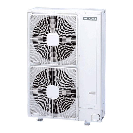
RAS-(3-6)HVNC1(E)
Hitachi RAS-(3-6)HVNC1(E) Manuals
Manuals and User Guides for Hitachi RAS-(3-6)HVNC1(E). We have
1
Hitachi RAS-(3-6)HVNC1(E) manual available for free PDF download: Service Manual
Hitachi RAS-(3-6)HVNC1(E) Service Manual (499 pages)
Brand:
Hitachi
| Category:
Air Conditioner
| Size: 74.07 MB
Table of Contents
Service Manual
1
Contents
3
Table of Contents
5
General Index
5
1 General Information
15
General Information
16
General Notes
16
IVX Premium
16
IVX Standard
16
Introduction
16
Environment-Friendly Units
17
Safety
18
Applied Symbols
18
Norms and Regulations
18
Product Guide
19
Classification of Outdoor Unit Models
19
Classification of Indoor Unit Models
19
Product Guide: Outdoor Units
20
Outdoor Unit Accessory Code List
21
Product Guide: Indoor Units & Complementary Systems
23
RCI and RCIM Indoor Units
23
RCD and RPC Indoor Units
24
RPC, RPI and RPIM Indoor Units
25
RPK, RPF and RPFI Indoor Units
26
Product Line-Up: KPI Energy / Heat Recovery Unit
26
Product Line-Up: DX-Interface
27
2 Unit Installation
29
Safety Summary
30
Transportation of Outdoor Unit
31
Hanging Method
31
Gross Weight
31
Center of Gravity
32
Factory-Supplied Accessories for RAS-12HN(P/C)
33
Installation Space (Initial Ckeck)
34
Basic Sizes
34
Ras-(2-2.5)Hvnp1 / Ras-3Hvnc1
35
Ras-(3-12)H(V)Np(1)(E) / Ras-3Hvnc1 / Ras-12Hnc
36
Ras-(4-6)H(V)Nc1E
39
Place Provision for RAS-(2-2.5)HVNP1 / RAS-3HVNC1
41
Place Provision for RAS-3HVNP1E / RAS-(4-6)H(V)N(P/C)1E / RAS-(8-10)HN(P/C)E / RAS-12HN(P/C)
43
Recommended Metal Plate Size
44
Fix Unit to the Wall
44
Suspended Unit
45
Installing Location Where the Unit will be Exposed to Strong Wind
45
Optional Parts and Installation for RAS-(2-2.5)HVNP1 / RAS-3HVNC1
46
Air Flow Guide Wind Guard and Snow Protection Hood
46
Air Flow Guide
46
Locations of Fixing Holes
47
One Flow Guide Installation
47
Service Space (in Case of Upward Air Discharge)
47
Wind Guard
48
Attaching Example of Air Wind Guard
48
Two Windguard Covers Installation
48
Service Space
48
Snow Protection Hood
49
Air Discharge Hood
49
Rear Suction Hood
49
Left Suction Hood
49
Attaching Example of Snow Protection Hood
50
Specifications of Snow Protection Hood
50
Optional Parts and Installation RAS-3HVNP1E
51
Attaching Example of Air Flow Guide
51
One Windguard Cover Installation
53
Optional Parts and Installation RAS-(4-6)H(V)NC1E
56
Optional Parts and Installation RAS-(4-6)H(V)NPE / RAS-(8-10)HN(P/C)E
63
Two Flow Guides Installation
64
Optional Parts and Installation RAS-12HN(P/C)
69
3 Piping Work and Refrigerant Charge
75
General Notes before Performing Pipe Work
76
Piping Materials
76
Piping Connection
76
Insulation
77
Three Principles on Refrigerant Piping Work
78
Suspension of Refrigerant Piping
78
Brazing Work
79
Piping Connection for Outdoor Unit
80
Ras-(2-2.5)Hvnp1 / Ras-3Hvnc1
80
Ras-3Hvnp1E / Ras-(4-6)H(V)N(P/C)1E / Ras-(8-10)Hn(P/C)E / Ras-12Hn(P/C)
81
For the Front and Side Piping
82
For the Downward Piping
82
For the Rear Side Piping
83
Outdoor Unit Stop Valve
84
Refrigerant Piping Range
86
Refrigerant Piping Length
86
Piping System for Header Branch
86
Maximum Refrigerant Piping Length
87
Piping System for Line Branch
89
Combinations of Piping Size and Piping Length
90
Refrigerant Piping Size and Multikit/Distributor Selection
91
Line Branch System
93
System Installation
94
Height Difference between Indoor Units and Distributor
94
Installing Distributor
95
Connecting Flare Adapter
96
Refrigerant Charge
97
Caution of the Pressure by Check Joint
98
Refrigerant Charge Quantity
98
Refrigerant Charge before Shipment
98
Additional Refrigerant Charge Calculation Method
100
Additional Refrigerant Charge Calculation for Liquid Piping
100
Additional Refrigerant Charge Calculation for Indoor Unit
101
Calculation of Total Additional Refrigerant Charge
101
Charging Work
101
Total Refrigerant Charge of the System
101
Pump down Refrigerant
102
Caution in Case of Refrigerant Leakage
103
Maximum Permitted Concentration of Hydrofluorocarbon (HFC)
103
Calculation of Refrigerant Concentration
103
Compatibility with the Piping of Current Installations Where R22 or R407C Is Used
104
Installation Procedure for Existing Pipes
104
Conditions to Use a Existing Pipes with Cleaning Process
104
Conditions to Use a Existing Pipes Without Cleaning Process
104
When Existing Air-Conditioner Is a Product of Another Manufacturer
104
Renewal Kit Selection Model
106
Recommended Renewal Kit
106
Details of Renewal Kit
106
Drain Piping
110
Drain Discharging Boss
110
Connecting Procedure
110
4 Electrical Wiring
111
General Notes
112
General Check
112
Electrical Wiring Connection for the Outdoor Unit
114
Setting the DIP Switches for the Outdoor Unit
116
Quantity and Position of DIP Switches
116
Function of the of DIP Switches and RSW Switches
117
DSW2: Pipe Length Setting (Setting Is Required) / Optional Function Setting
118
DSW4 / RSW1: Refrigerant Cycle Number Setting (Setting Is Required)
119
DSW5: End Terminal Resistance (no Setting Is Required)
119
Setting for Transmission by Means of DSW4 / RSW1 and DSW5
119
DSW6: Setting of Multiple Indoor Units Operation (Setting Is Required)
120
Jumpers
121
Jumper Lead Setting (JP1~6)
121
Led’s Indication
121
Electrical Settings
122
Outdoor and Indoor Unit Electrical Wiring
122
Wire Size
123
Connection Wiring
123
Main Switch Protection
124
H-LINK II System
125
Features
125
Specifications
125
DIP Switch Setting for Twin, Triple and Quad Systems
126
Examples of the System of Connection between H-LINK and H-LINK II Units
127
Examples of H-LINK II System
128
System Control
130
Individual Operation
130
Simultaneous Operation
131
Electrical Wiring Diagrams
132
RAS-(2-2.5)HVNP1 / RAS-3HVNC1 (1~ 230V 50Hz)
132
RAS-3HVNP1E (1~ 230V 50Hz)
134
RAS-(4-6)HVNP1E (1~ 230V 50Hz)
136
RAS-(4-6)HNP1E (3N~ 400V 50Hz)
138
RAS-(4-6)HVNC1E (1~ 230V 50Hz)
140
RAS-(4-6)HNC1E (3N~ 400V 50Hz)
142
RAS-(8-10)HN(P/C)E (3N~ 400V 50Hz)
144
RAS-12HN(P/C) (3N~ 400V 50Hz)
146
5 Control System
149
Device Control System
150
Outdoor Units PCB
152
Ras-(2-2.5)Hvnp1 / Ras-3Hvnc1
152
Ras-3Hvnp1E
153
Ras-(4-6)H(V)Np1E
154
Ras-(4-6)H(V)Nc1E
155
Ras-(8-10)Hn(P/C)E
156
Ras-12Hn(P/C)
157
Protection and Safety Control
158
Compressor Protection
158
Safety and Control Device Setting for the Outdoor Units
158
Standard Operation Sequence
159
Cooling Operation
159
Dry Operation
161
Heating Operation
163
Automatic Cooling and Heating Operation
165
Defrost Operation Control
166
Defrosting Operation
166
Condition for Starting Defrost
167
Condition for Completing Defrost Operation
168
Standard Control Functions
169
Freezing Protection During Cooling Process or Dry Operation
169
Prevention Control for High Pressure Increase During Cooling Operation
170
Prevention Control for Excessively High Discharge Gas Temperature
171
Activation for Protection Device Control
172
Preheating Control of Compressor
173
Prevention Control for High Pressure Increase
174
6 Optional Functions
175
Optional External Input and Output Signals (by 7-Segment Display)
176
Available Ports
176
Specification of the Components for a Correct Installation
177
Available Optional External Signals
178
Output Signals (CN7)
180
Setting of the Optional Signals
181
Description of Optional Signals
182
Input Signals
182
Output Signals
184
Optional Functions (by 7-Segment Display)
185
Setting of the Optional Functions
185
Description of the Optional Functions
189
Control of the Indoor Unit Fan During Thermo-OFF in Heating Mode (FA)
189
Night Mode (Low Noise) (Ni)
189
Cancellation of Outdoor Ambient Temperature Limit (GS)
190
Change of Defrost Condition (Jo)
191
Slo (Fan Speed) Defrost Setting (Bj)
192
Cancellation of Outdoor Hot Start Limit
192
Long Piping Setting (Nu)
192
Compressor Frequency Control Target Value for Cooling (Control Function “Hc”)
192
Fixing on Demand Function (De)
193
Wave Function Setting (UE)
194
Cold Draft Protection 1 (Fb)
194
Cancellation of Hot Gas Bypass Control (3-12 HP Premium) (E1)
194
Forced Stoppage after Defrost Operation (“D5”)
194
Intermittent Operation of Outdoor Fan Motor (F1)(RAS-(4-6)H(V)NC1E Only)
195
Compressor Heater Control Mode (F3)
195
Optional Functions (by Remote Control Switch)
196
7 Test Run
205
Checking Procedure before the Test Run
206
About Insulation Resistance
207
Test Run Procedure Using the Remote Control Switch (PC-ART)
208
Test Run Procedure Using the Remote Control Switch (PC-ARF)
210
Test Run Procedure Using the Wireless Remote Control Switch (PC-LH3A/B)
213
Test Run Procedure from the Outdoor Unit Side
215
Check List on Test Run
217
Check List on Compressor
218
Additional Information for “Check List on Compressor”
219
8 Troubleshooting
221
Initial Troubleshooting
222
Checking by Means of the 7-Segment Display
222
Failure of the Power Supply to the Indoor Unit and the Remote Control Switch
223
Abnormal Transmission between the Remote Control Switch and the Indoor Unit
224
Abnormal Operation of the Devices
224
Troubleshooting Procedure
230
Alarm Display
230
On-Screen Displays During Abnormal Operation
230
Alarm Codes for the Outdoor and Indoor Units
231
Troubleshooting by Alarm Code for the Outdoor and Indoor Units
233
Abnormal Transmission between the Indoor Units and the Outdoor Unit for RAS-(2-2.5)HVNP1 / RAS-3HVNC1
238
Abnormal Transmission between the Indoor Units and the Outdoor Unit for RAS-(3-12)H(V)N(P/C)(1)(E)
241
Abnormal Transmission between Inverter PCB and Outdoor PCB1
245
Code Abnormal Operation of Picking up Phase Signal
248
Excessively Low Voltage or Excessively High Voltage for the Inverter
249
Decrease of Discharge Gas Superheat
251
Excessively High Discharge Gas Temperature at the Top of Compressor
253
Abnormal Operation of Thermistor for the Indoor Unit Air Inlet Temperature (Air Inlet Thermistor)
254
Abnormal Operation of the Thermistor for the Indoor Discharge Air Temperature (Air Outlet Thermistor)
255
Abnormal Operation of the Thermistor for the Indoor Unit Heat Exchanger Liquid Pipe Temperature (Freeze Protection Thermistor)
256
Abnormal Operation of the Thermistor for the Indoor Unit Heat Exchanger Gas Pipe Temperature (Gas Piping Thermistor)
257
Activation of the Protection Device for the Indoor Fan Motor (Except RCI-FSN3, RCIM-FSN3, RPC- FSN3 and RPK-FSN(H)3M)
258
Activation of the Protection Device for the Indoor Fan Motor (RCI-FSN3, RCIM-FSN3, RPC-FSN3)
259
Activation of the Protection Device for the Indoor Fan Motor (RPK)
260
Abnormality of Thermistor for Discharge Gas Temperature (Compressor Thermistor)
261
Abnormality of High Pressure Sensor for RAS-(3-12)H(V)NP(1)(E)
262
Abnormal Operation of the Thermistor for the Outdoor Temperature (Outdoor Unit Ambient Thermistor)
263
Abnormal Operation of the Thermistor for the Evaporating Temperature During the Heating Process (Outdoor Unit)
264
Incorrect Capacity Setting or Combined Capacity between Indoor Units and Outdoor Unit
265
Incorrect Indoor Number Setting
266
Abnormality of Protective Circuit for Protection (Outdoor Unit)
267
Cooling Overload (High Pressure Switch will be Activated) for RAS-(2-2.5)HVNP1 and RAS-3HVNC1
268
Heating Overload (High Pressure Switch will be Activated) for RAS-(2-2.5)HVNP1 and RAS-3HVNC1
270
Activation of High Pressure Increase Protection Device
272
Activation to Protect System from Excessively Low Suction Pressure (Protection from Vacuum Operation)
273
Overcurrent Protection Activation for RAS-(2-2.5)HVNP1 and RAS-3HVNC1
274
Overcurrent Protection Activation for RAS-(3-12)H(V)N(P/C)(1)(E)
275
Abnormal Operation of the Current Sensor (RAS-(2-2.5)HVNP1 / RAS-3HVNC1)
276
Abnormal Operation of the Current Sensor (RAS-(3-6)H(V)N(P/C)1E)
277
Abnormal Operation of the Current Sensor (RAS-(8-12)HN(P/C)(E))
278
Activation of Transistor Module (RAS-(2-2.5)HVNP1 / RAS-3HVNC1)
279
Activation of Transistor Module (Except for (RAS-(2-2.5)HVNP1 / RAS-3HVNC1))
280
Activation of Transistor Module (RAS-(8-12)HN(P/C)(E))
282
Abnormality of Inverter Fin Temperature (RAS-3HVNP1E / RAS-(4-6)H(V)N(P/C)1E)
284
Abnormality of Inverter Fin Temperature (RAS-(8-12)HN(P/C)(E))
285
Abnormality of Inverter Module
286
Abnormality of Fan Motor Protection (DC Fan Motor)
287
Incorrect Setting of Unit Model Code
288
Incorrect Setting of Unit and Refrigerant Cycle Number
288
Incorrect Setting of Indoor Unit Number for H-LINK Type
288
Alarm Codes for the KPI (E/H/X)3E Series and DX Interface
289
Troubleshooting in Check Mode
290
Troubleshooting Using the Remote Controller PC-ART
290
Temperature Indication
292
Indication of Micro-Computer Input/Output
293
Indication of Unit Stoppage Cause
293
Abnormal Operation Occurrence Counter
294
Indication of Automatic Louver Condition
294
Compressor Pressure/Frequency Indication
294
Indoor Unit Capacity Indication
294
Expansion Opening Indication
295
Estimated Electric Current Indication
295
Contents of the Check Mode 2
296
Self-Checking Procedure of PCB by Means of the Remote Control Switch
297
Self-Checking Procedure of the Remote Control Switch
299
Troubleshooting Using the Remote Controller PC-ARF
301
Checking Procedure of PCB by Means of the Remote Control Switch
303
Result of Check Table
303
Troubleshooting Using the 7 Segment Display
306
Simple Checking by 7-Segment Display
306
Checking Method by 7-Segment Display
306
Check Mode Items
306
Cause of Indoor Unit Stoppage
310
Cancellation of Forced Thermo off
311
Cause of Inverter Stoppage
311
Table of Capacity Codes of Indoor Unit
311
Protection Control Code on 7-Segment Display
312
Activating Condition of Protection Control Code
313
Checking Procedure for Main Parts
315
Checking Procedure for the PCB (PCB1 Ref PO101)
315
Checking Procedure for the DIP-IPM Inverter
317
Inverter Module Checking Procedure
317
ACT Circuit of Inverter PCB
318
Checking Method of Resistance for Inrush Current Prevention (Built-In Thermal Fuse)
319
Checking Method of Fuse for Fan Motor Protection (EF1)
320
High Voltage Discharge Work for Replacing Parts
320
Transistor Module Checking Procedure
321
Diode Module Checking Procedure
322
Checking Procedure for the Capacitors CB1 & CB2
323
Checking Procedeure for the DC Fan Motor
324
Procedure in Case of Error Diagnosis
324
Checking Procedure for the AC Fan Motor
325
Checking Procedure for the Electronic Expansion Valve for Indoor and Outdoor Units
325
Checking Procedure for Other Parts
326
Checking Procedure for the Reversing Valve
327
Actions of 4-Way Solenoid Valve
327
Monostable Solenoid Operation Type
327
Bistable Solenoid Operation Type (Pulse-Activated)
328
Checking Procedure for the Compressor
330
9 Spare Parts
333
Ras-(2-2.5)Hvnp1
334
Cycle and Structural Parts
334
Location of Spare Parts in the Unit
334
Parts Table
335
Ras-3Hvnc1
336
Cycle and Structural Parts
336
Parts Table
337
Ras-3Hvnp1E
338
Cycle and Structural Parts
338
Electrical Parts
339
Parts Name
340
Ras-(4-6)H(V)Np1E
341
Cycle and Structural Parts
341
Electrical Parts
342
Parts Name
344
Ras-(4-6)H(V)Nc1E
346
Cycle and Structural Parts
346
Electrical Parts
348
Parts Name
350
Ras-(8-10)Hn(P/C)E
352
Cycle and Structural Parts
352
Electrical Parts
354
Servicing
363
Ras-3Hvnc1
368
Removing Pipe Cover
368
Removing Front Cover
368
Removing the Compressor
369
Removing High Pressure Switch and Pressure Switch for Control
371
Removing Four-Way Valve Coil
371
Removing Electronic Expansion Valve Coil
372
Removing Electrical Components
373
Removing Display PCB
373
Removing Other Electrical Components
374
Removing Service Cover
375
Remove Outlet Grille
375
Removing Upper Cover
376
Removing Bottom Service Cover and Rear Cover
376
Removing Outdoor Fan Motor
377
Removing Electrical Box
378
Removing the High Pressure Switch and Pressure Switch for Control
381
High Pressure Switch and Pressure Switch for Control
381
Low Pressure Switch
381
Opening Electrical Box (P Plate)
382
Removing Reversing Valve Coil
382
Removing Solenoid Valve Coil (SVC)
383
Removing Reversing Valve
383
Removing Electronic Expansion Valve and Solenoid Valve
384
Removing Control PCB (PCB1)
384
Removing Inverter Module
384
Ras-(4-6)H(V)Np1E
386
Removing the Bottom Service Cover and Rear Cover
387
Removing Reversing and Solenoid Valves Coils
420
Removing Solenoid Valves
422
Removing Control PCB (PCB1 and PCB3)
423
Removing Diode Module (DM)
423
Removing Transistor Module (IPM)
424
Electrical Checks of Main Parts
467
Specifications of Inverter
468
Inverter Time Chart
470
Protective Function
471
Excessive High or Low Voltage for Inverter
471
Abnormality of Current Sensor
471
Overcurrent Protection for Inverter
471
Fin Temperature Increase
472
Earth Detection
472
Overload Control
472
Thermistor
473
Thermistors for the Outdoor Unit
473
Thermistors for 4-6HP Standard
473
Thermistor for Discharge Gas Temperature (THM9)
474
Thermistor for Outdoor Ambient Temperature (THM7)
474
Thermistor for Evaporating Temperature of Outdoor Unit in Heating Operation (for Defrosting) (THM8)
475
Thermistor for Condensing Temperature of RAS-4H(V)RNS3E Outdoor Unit (THM10)
475
Thermistor for Inverter Fin Temperature (THMI)
475
Electronic Expansion Valve
476
High Pressure Protection Device
477
Noise Filter (NF)
479
Noise Filter for 3N~ (400V/50Hz)
479
Noise Filter for 1~ (230V/50Hz)
480
Capacitor (CB1 CB2) 8/10/12 HP Only
481
Reactor (DCL) for 3N~ (400V/50Hz)
482
Reactor (DCL) for 1~ (230V/50Hz)
482
Scroll Compressor
483
Reliable Mechanism for Low Vibrating and Low Sound
483
Principle of Compression
483
Maintenance Notes
485
Checking the Power Source and the Wiring Connection
486
Burnt-Out Compressor Due to an Insufficient Refrigerant Charge
486
Insufficient Cooling Performance When a Long Piping Is Applied
487
Abnormally High Operation Sound (in the Ceiling Type Indoor Unit)
487
Alarm Code “03”
488
Not Cooling Well Due to Insufficient Installation Space for the Outdoor Unit
488
Maintenance Work
489
For the Indoor Unit and the Outdoor Unit
489
For the Outdoor Unit
489
Service and Maintenance Record
490
Service and Maintenance Record Using the 7-Segment Display
491
Service and Maintenance Record by Remote Control Switch
493
Pump-Down Method for Replacing the Compressor
494
Advertisement
Advertisement
Related Products
Hitachi RAS-(3-6)HVRNM2E
Hitachi RAS-36FSXN1E
Hitachi RAS-36FSXNH
Hitachi RAS-36FSXNHE
Hitachi RAS-36FSXN
Hitachi RAS-30CHP6
Hitachi RAS-3HVRNS
Hitachi RAS-32FSXN1E-P
Hitachi RAS-38FSXN
Hitachi RAS-35YHA6
Hitachi Categories
Projector
Air Conditioner
Drill
Power Tool
TV
More Hitachi Manuals
Login
Sign In
OR
Sign in with Facebook
Sign in with Google
Upload manual
Upload from disk
Upload from URL