Sign In
Upload
Manuals
Brands
HP Manuals
Laptop
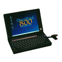
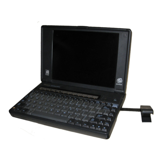
OmniBook 800CT
HP OmniBook 800CT Manuals
Manuals and User Guides for HP OmniBook 800CT. We have
3
HP OmniBook 800CT manuals available for free PDF download: Service Manual
HP OmniBook 800CT Service Manual (119 pages)
Hewlett-Packard Laptop Service Manual
Brand:
HP
| Category:
Laptop
| Size: 3.35 MB
Table of Contents
Service Manual
1
Table of Contents
4
List of Figures
6
Introduction
8
Product Overview
10
What's New
10
Product Features
10
Figure 1 - Omnibook 800 External Features
12
Figure 2 - Omnibook 800 External Features (Continued)
12
Product Features
12
Product at a Glance
13
Figure 3 - Exploded Diagram
13
Table 1 - Parts Identification
14
Product Comparisons
15
Troubleshooting
22
Power-On Self-Test
23
Beep Codes
23
Table 2 - POST Beep Codes
23
Display Codes
24
Table 3 - POST Display Codes
24
Omnibook Diagnostics
26
Running the Diagnostics Program
26
Main Diagnostic Screen
26
Figure 4 - Main Diagnostic Screen
27
Special Test Hardware Requirements
28
Loop Back Connectors
29
Figure 5 - Serial Loop Back Connector
29
Figure 6 - Parallel Loop Back Connector
29
Figure 7 - SCSI Loop Back Connector
29
Figure 8 - Sycard Solder Bridges
30
Command Line Options
31
Table 4 - Diagnotic Command Line Options
31
User Interface Commands
32
Table 5 - Diagnostic Test Selection Commands
32
Table 6 - Diagnostic Commands for Toggling Settings
33
Table 7 - Diagnostic Hidden Commands
34
Table 8 - Diagnostic Test Parameters
35
Details on Using the Diagnostic Tests
36
Figure 9 - Sycard Test Results
38
Figure 10 - Keyboard Test Screen
40
Figure 11 - Mouse Test Screen (Text Mode)
42
Figure 12 - Mouse Test Screen (Graphics Mode)
43
Figure 13 - Dock Keyboard Test Screen
46
Desktop Management Interface (DMI)
47
Description of DMI
47
Contents of the DMI Package
47
Figure 14 - DMI Components
48
Setup and Configuration
50
SCU Main Screen
50
System Menu Screen
51
Table 9 - System Menu Settings
51
Password Configuration
53
Table 10 - System Password Matrix
53
Input/Output Menu Screen
54
Table 11 - Input/Output Menu Settings
54
Power Menu Screen
56
Table 12 - Power Menu Settings
56
Default Menu Screen
57
Table 13 - Default Menu Settings
57
Exit Menu Screen
58
Table 14 - Exit Menu Settings
58
Troubleshooting Tips
59
Omnibook Components
59
Table 15 - Omnibook Troubleshooting Tips
59
CD ROM Drive Troubleshooting
64
Table 16 - CD-ROM Troubleshooting Tips
64
Resolving Docking Station Operating Problems
65
Resolving Omnibook Docking Problems
66
Hardware Repair
68
Battery (End User Replaceable)
69
Figure 15 - Removing the Battery
69
Memory (End User Replaceable)
70
Figure 16 - 8- and 16-MB Memory Modules
70
Figure 17 - New and Old 32-MB Memory Module (Respectively)
70
Figure 18 - Removing the Memory Module
71
Hard Disk Drive (End User Replaceable)
72
Figure 19 - Hard Drive Screws
72
Figure 20 - Folding the Keyboard Open
73
Figure 21 - Hard Drive Removal
73
Figure 22 - Hard Drive Removal (Continued)
74
Figure 23 - Hard Drive Insulator Flap
74
Figure 24 - Inserting the Hard Drive
75
Figure 25 - Proper Keyboard Flex Cable Position
75
Figure 26 - IBM and Toshiba Hard Drive Breather Holes (Respectively)
76
Hard Disk Drive Breather Holes
76
Mouse (End User Replaceable)
77
Figure 27 - Removing the Mouse
77
Small Parts (End User Replaceable)
78
Battery Latch
78
I/O Door
78
Memory Cover
78
PCMCIA Card Tray
78
Rubber Feet
78
Keyboard (HP Authorized Service Providers Only)
79
Figure 28 - Keyboard Screws
79
Figure 29 - Folding the Keyboard Open
79
Figure 30 - Keyboard Flex Cables
80
Figure 31 - Keyboard Flex Cable Placement
80
Display (HP Authorized Service Providers Only)
81
Figure 32 - Bottom Case Screws and Rubber Feet
81
Figure 33 - Keyboard Support Plate Screws
82
Figure 34 - Display Flex Cables
83
Figure 35 - Top Case and Display Removal
84
Figure 36 - Intel Inside Sticker Placement
85
CPU (HP Authorized Service Providers Only)
86
Figure 37 - Removing the CPU
86
Figure 38 - Heat Transfer Disk and Keyboard Support Insulator
87
Figure 39 - CPU Thermal Coupling
87
Heat Transfer Disk
87
Logic PCA Board (HP Authorized Service Providers Only)
89
Electronic Serial Number
89
Figure 40 - Logic PCA Removal
90
Figure 41 - Grommet and Bushing Placement
91
Paw Active (HP Authorized Service Providers Only)
92
Figure 42 - Paw Active Removal
92
Other Components and Accessories (HP Authorized Service Providers Only)
93
Appendix A - Technical Specifications
97
Mass Storage Specifications
97
Hard Disk Drive
97
Floppy Disk Drive
97
Table 17 - Hard Disk Drive Specifications
97
CD-ROM Drive
98
Table 18 - Floppy Disk Drive Specifications
98
Table 19 - CD-ROM Drive Specifications
98
System Resources
99
System Interrupts (Irqs)
99
Table 20 - Interrupts for F1171 - F1175
99
Table 21 - Interrupts for F1360
99
DMA Channels
100
Memory Map
100
Table 22 - DMA Channels for F1171 - F1175, and F1360
100
Table 23 - Memory Map for F1171 - F1175
100
Table 24 - Memory Map for F1360
100
I/O Addresses
101
Table 25 - I/O Address for F1171 - F1175
101
Table 26 - I/O Addresses for F1360
101
Appendix B - Hewlett-Packard Password Removal Policy
102
Appendix C - Hewlett-Packard TFT Display Quality Statement
104
Appendix D - Omnibook Diagnostics BIOS Checksums
105
Table 27 - Omnibook F1171 - F1175 BIOS Checksums
105
Table 28 - Omnibook F1360 BIOS Checksums
105
Appendix E - Omnibook Diagnostics Error Messages
106
Hewlett-Packard Supplied Test Messages
106
Watergate Software Supplied Test Messages
109
Appendix F - Part Numbers
114
Advertisement
HP OmniBook 800CT Service Manual (119 pages)
HP OmniBook Service Manual
Brand:
HP
| Category:
Laptop
| Size: 3.35 MB
Table of Contents
Service Manual
1
Table of Contents
4
List of Figures
6
Introduction
8
Product Overview
10
What's New
10
Product Features
10
Figure 1 - Omnibook 800 External Features
12
Figure 2 - Omnibook 800 External Features (Continued)
12
Product Features
12
Product at a Glance
13
Figure 3 - Exploded Diagram
13
Table 1 - Parts Identification
14
Product Comparisons
15
Troubleshooting
22
Power-On Self-Test
23
Beep Codes
23
Table 2 - POST Beep Codes
23
Display Codes
24
Table 3 - POST Display Codes
24
Omnibook Diagnostics
26
Running the Diagnostics Program
26
Main Diagnostic Screen
26
Figure 4 - Main Diagnostic Screen
27
Special Test Hardware Requirements
28
Loop Back Connectors
29
Figure 5 - Serial Loop Back Connector
29
Figure 6 - Parallel Loop Back Connector
29
Figure 7 - SCSI Loop Back Connector
29
Figure 8 - Sycard Solder Bridges
30
Command Line Options
31
Table 4 - Diagnotic Command Line Options
31
User Interface Commands
32
Table 5 - Diagnostic Test Selection Commands
32
Table 6 - Diagnostic Commands for Toggling Settings
33
Table 7 - Diagnostic Hidden Commands
34
Table 8 - Diagnostic Test Parameters
35
Details on Using the Diagnostic Tests
36
Figure 9 - Sycard Test Results
38
Figure 10 - Keyboard Test Screen
40
Figure 11 - Mouse Test Screen (Text Mode)
42
Figure 12 - Mouse Test Screen (Graphics Mode)
43
Figure 13 - Dock Keyboard Test Screen
46
Desktop Management Interface (DMI)
47
Description of DMI
47
Contents of the DMI Package
47
Figure 14 - DMI Components
48
Setup and Configuration
50
SCU Main Screen
50
System Menu Screen
51
Table 9 - System Menu Settings
51
Password Configuration
53
Table 10 - System Password Matrix
53
Input/Output Menu Screen
54
Table 11 - Input/Output Menu Settings
54
Power Menu Screen
56
Table 12 - Power Menu Settings
56
Default Menu Screen
57
Table 13 - Default Menu Settings
57
Exit Menu Screen
58
Table 14 - Exit Menu Settings
58
Troubleshooting Tips
59
Omnibook Components
59
Table 15 - Omnibook Troubleshooting Tips
59
CD ROM Drive Troubleshooting
64
Table 16 - CD-ROM Troubleshooting Tips
64
Resolving Docking Station Operating Problems
65
Resolving Omnibook Docking Problems
66
Hardware Repair
68
Battery (End User Replaceable)
69
Figure 15 - Removing the Battery
69
Memory (End User Replaceable)
70
Figure 16 - 8- and 16-MB Memory Modules
70
Figure 17 - New and Old 32-MB Memory Module (Respectively)
70
Figure 18 - Removing the Memory Module
71
Hard Disk Drive (End User Replaceable)
72
Figure 19 - Hard Drive Screws
72
Figure 20 - Folding the Keyboard Open
73
Figure 21 - Hard Drive Removal
73
Figure 22 - Hard Drive Removal (Continued)
74
Figure 23 - Hard Drive Insulator Flap
74
Figure 24 - Inserting the Hard Drive
75
Figure 25 - Proper Keyboard Flex Cable Position
75
Figure 26 - IBM and Toshiba Hard Drive Breather Holes (Respectively)
76
Hard Disk Drive Breather Holes
76
Mouse (End User Replaceable)
77
Figure 27 - Removing the Mouse
77
Small Parts (End User Replaceable)
78
Battery Latch
78
I/O Door
78
Memory Cover
78
PCMCIA Card Tray
78
Rubber Feet
78
Keyboard (HP Authorized Service Providers Only)
79
Figure 28 - Keyboard Screws
79
Figure 29 - Folding the Keyboard Open
79
Figure 30 - Keyboard Flex Cables
80
Figure 31 - Keyboard Flex Cable Placement
80
Display (HP Authorized Service Providers Only)
81
Figure 32 - Bottom Case Screws and Rubber Feet
81
Figure 33 - Keyboard Support Plate Screws
82
Figure 34 - Display Flex Cables
83
Figure 35 - Top Case and Display Removal
84
Figure 36 - Intel Inside Sticker Placement
85
CPU (HP Authorized Service Providers Only)
86
Figure 37 - Removing the CPU
86
Figure 38 - Heat Transfer Disk and Keyboard Support Insulator
87
Figure 39 - CPU Thermal Coupling
87
Heat Transfer Disk
87
Logic PCA Board (HP Authorized Service Providers Only)
89
Electronic Serial Number
89
Figure 40 - Logic PCA Removal
90
Figure 41 - Grommet and Bushing Placement
91
Paw Active (HP Authorized Service Providers Only)
92
Figure 42 - Paw Active Removal
92
Other Components and Accessories (HP Authorized Service Providers Only)
93
Appendix A - Technical Specifications
97
Mass Storage Specifications
97
Hard Disk Drive
97
Floppy Disk Drive
97
Table 17 - Hard Disk Drive Specifications
97
CD-ROM Drive
98
Table 18 - Floppy Disk Drive Specifications
98
Table 19 - CD-ROM Drive Specifications
98
System Resources
99
System Interrupts (Irqs)
99
Table 20 - Interrupts for F1171 - F1175
99
Table 21 - Interrupts for F1360
99
DMA Channels
100
Memory Map
100
Table 22 - DMA Channels for F1171 - F1175, and F1360
100
Table 23 - Memory Map for F1171 - F1175
100
Table 24 - Memory Map for F1360
100
I/O Addresses
101
Table 25 - I/O Address for F1171 - F1175
101
Table 26 - I/O Addresses for F1360
101
Appendix B - Hewlett-Packard Password Removal Policy
102
Appendix C - Hewlett-Packard TFT Display Quality Statement
104
Appendix D - Omnibook Diagnostics BIOS Checksums
105
Table 27 - Omnibook F1171 - F1175 BIOS Checksums
105
Table 28 - Omnibook F1360 BIOS Checksums
105
Appendix E - Omnibook Diagnostics Error Messages
106
Hewlett-Packard Supplied Test Messages
106
Watergate Software Supplied Test Messages
109
Appendix F - Part Numbers
114
HP OmniBook 800CT Service Manual (118 pages)
Hewlett-Packard Notebook PC Service Manual
Brand:
HP
| Category:
Laptop
| Size: 4.5 MB
Table of Contents
Service Manual
1
Table of Contents
3
List of Figures
5
Introduction
7
Product Overview
9
What's New
9
Product Features
9
Figure 1 - Omnibook 800 External Features
11
Figure 2 - Omnibook 800 External Features (Continued)
11
Product Features
11
Product at a Glance
12
Figure 3 - Exploded Diagram
12
Table 1 - Parts Identification
13
Product Comparisons
14
Troubleshooting
21
Power-On Self-Test
22
Beep Codes
22
Table 2 - POST Beep Codes
22
Display Codes
23
Table 3 - POST Display Codes
23
Omnibook Diagnostics
25
Running the Diagnostics Program
25
Main Diagnostic Screen
25
Figure 4 - Main Diagnostic Screen
26
Special Test Hardware Requirements
27
Loop Back Connectors
28
Figure 5 - Serial Loop Back Connector
28
Figure 6 - Parallel Loop Back Connector
28
Figure 7 - SCSI Loop Back Connector
28
Figure 8 - Sycard Solder Bridges
29
Command Line Options
30
Table 4 - Diagnotic Command Line Options
30
User Interface Commands
31
Table 5 - Diagnostic Test Selection Commands
31
Table 6 - Diagnostic Commands for Toggling Settings
32
Table 7 - Diagnostic Hidden Commands
33
Table 8 - Diagnostic Test Parameters
34
Details on Using the Diagnostic Tests
35
Figure 9 - Sycard Test Results
37
Figure 10 - Keyboard Test Screen
39
Figure 11 - Mouse Test Screen (Text Mode)
41
Figure 12 - Mouse Test Screen (Graphics Mode)
42
Figure 13 - Dock Keyboard Test Screen
45
Desktop Management Interface (DMI)
46
Description of DMI
46
Contents of the DMI Package
46
Figure 14 - DMI Components
47
Setup and Configuration
49
SCU Main Screen
49
System Menu Screen
50
Table 9 - System Menu Settings
50
Password Configuration
52
Table 10 - System Password Matrix
52
Input/Output Menu Screen
53
Table 11 - Input/Output Menu Settings
53
Power Menu Screen
55
Table 12 - Power Menu Settings
55
Default Menu Screen
56
Table 13 - Default Menu Settings
56
Exit Menu Screen
57
Table 14 - Exit Menu Settings
57
Troubleshooting Tips
58
Omnibook Components
58
Table 15 - Omnibook Troubleshooting Tips
58
CD ROM Drive Troubleshooting
63
Table 16 - CD-ROM Troubleshooting Tips
63
Resolving Docking Station Operating Problems
64
Resolving Omnibook Docking Problems
65
Hardware Repair
67
Battery (End User Replaceable)
68
Figure 15 - Removing the Battery
68
Memory (End User Replaceable)
69
Figure 16 - 8- and 16-MB Memory Modules
69
Figure 17 - New and Old 32-MB Memory Module (Respectively)
69
Figure 18 - Removing the Memory Module
70
Hard Disk Drive (End User Replaceable)
71
Figure 19 - Hard Drive Screws
71
Figure 20 - Folding the Keyboard Open
72
Figure 21 - Hard Drive Removal
72
Figure 22 - Hard Drive Removal (Continued)
73
Figure 23 - Hard Drive Insulator Flap
73
Figure 24 - Inserting the Hard Drive
74
Figure 25 - Proper Keyboard Flex Cable Position
74
Figure 26 - IBM and Toshiba Hard Drive Breather Holes (Respectively)
75
Hard Disk Drive Breather Holes
75
Mouse (End User Replaceable)
76
Figure 27 - Removing the Mouse
76
Small Parts (End User Replaceable)
77
Battery Latch
77
I/O Door
77
Memory Cover
77
PCMCIA Card Tray
77
Rubber Feet
77
Keyboard (HP Authorized Service Providers Only)
78
Figure 28 - Keyboard Screws
78
Figure 29 - Folding the Keyboard Open
78
Figure 30 - Keyboard Flex Cables
79
Figure 31 - Keyboard Flex Cable Placement
79
Display (HP Authorized Service Providers Only)
80
Figure 32 - Bottom Case Screws and Rubber Feet
80
Figure 33 - Keyboard Support Plate Screws
81
Figure 34 - Display Flex Cables
82
Figure 35 - Top Case and Display Removal
83
Figure 36 - Intel Inside Sticker Placement
84
CPU (HP Authorized Service Providers Only)
85
Figure 37 - Removing the CPU
85
Figure 38 - Heat Transfer Disk and Keyboard Support Insulator
86
Figure 39 - CPU Thermal Coupling
86
Heat Transfer Disk
86
Logic PCA Board (HP Authorized Service Providers Only)
88
Electronic Serial Number
88
Figure 40 - Logic PCA Removal
89
Figure 41 - Grommet and Bushing Placement
90
Paw Active (HP Authorized Service Providers Only)
91
Figure 42 - Paw Active Removal
91
Other Components and Accessories (HP Authorized Service Providers Only)
92
Appendix A - Technical Specifications
96
Mass Storage Specifications
96
Hard Disk Drive
96
Floppy Disk Drive
96
Table 17 - Hard Disk Drive Specifications
96
CD-ROM Drive
97
Table 18 - Floppy Disk Drive Specifications
97
Table 19 - CD-ROM Drive Specifications
97
System Resources
98
System Interrupts (Irqs)
98
Table 20 - Interrupts for F1171 - F1175
98
Table 21 - Interrupts for F1360
98
DMA Channels
99
Memory Map
99
Table 22 - DMA Channels for F1171 - F1175, and F1360
99
Table 23 - Memory Map for F1171 - F1175
99
Table 24 - Memory Map for F1360
99
I/O Addresses
100
Table 25 - I/O Address for F1171 - F1175
100
Table 26 - I/O Addresses for F1360
100
Appendix B - Hewlett-Packard Password Removal Policy
101
Appendix C - Hewlett-Packard TFT Display Quality Statement
103
Appendix D - Omnibook Diagnostics BIOS Checksums
104
Table 27 - Omnibook F1171 - F1175 BIOS Checksums
104
Table 28 - Omnibook F1360 BIOS Checksums
104
Appendix E - Omnibook Diagnostics Error Messages
105
Hewlett-Packard Supplied Test Messages
105
Watergate Software Supplied Test Messages
108
Appendix F - Part Numbers
113
Advertisement
Advertisement
Related Products
HP OmniBook 800CCT
HP OmniBook 800CS/CT
HP Presario 800AP
HP OmniBook 800CS
HP Compaq 800c
HP Compaq Presario,Presario 801KR
HP Compaq Presario,Presario 801TC
HP Compaq Presario,Presario 802TC
HP Compaq Presario,Presario 803AP
HP Compaq Presario,Presario 80XL202
HP Categories
Desktop
Laptop
Server
Monitor
Switch
More HP Manuals
Login
Sign In
OR
Sign in with Facebook
Sign in with Google
Upload manual
Upload from disk
Upload from URL