Sign In
Upload
Manuals
Brands
IBM Manuals
Switch
4002-Y4B
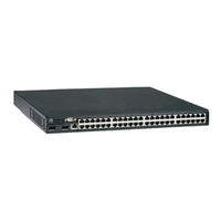
IBM 4002-Y4B Manuals
Manuals and User Guides for IBM 4002-Y4B. We have
1
IBM 4002-Y4B manual available for free PDF download: Installation And User Manual
IBM 4002-Y4B Installation And User Manual (96 pages)
IBM y-series of Ethernet Switches
Brand:
IBM
| Category:
Switch
| Size: 2.18 MB
Table of Contents
Table of Contents
5
Figures
7
Tables
9
Preface
11
Safety Notices
11
Safety Notices and Labels
11
Notes
12
Attention Notices
12
Caution Notices
12
Danger Notices
13
Safety Labels
16
Rack Safety
18
Rack Installation
18
Rack Relocation (19" Rack)
19
Product Recycling and Disposal
19
Product Documents
20
Software Documents
20
Comparable IBM and Brocade Products
21
Accessibility Features for the IBM Y-Series of Ethernet Switches
23
Accessibility Features
23
Keyboard Navigation
23
Vendor Software
23
Related Accessibility Information
24
IBM and Accessibility
24
Getting Help
24
Taiwan Contact Information
24
Audience
25
How to Send Your Comments
25
Text Formatting
25
Chapter 1. Product Overview
27
IBM Y-Series of Ethernet Switches
27
2-Y2A and Y2C Front Panel
28
2-Y4A and Y4C Front Panel
28
2-Y2B Front Panel
28
2-Y4B Front Panel
28
Control Features
29
2-Y2B and 4002-Y4B Rear Panel
29
Power Supply and Fan Tray Labels for
29
Network Interfaces for 4002-Y2A, Y4A, Y2C, and Y4C
30
Network Interfaces for 4002-Y2B and 4002-Y4B
30
Out-Of-Band 10/100/1000 Mbe RJ45 Management Interface
30
Serial Management Interface (DB9 Console Port)
30
SFP Interfaces
31
Stack Unit Slots for Y-Series Devices
31
Optional Four-Port 100/1000 Mbps SFP and 10 Gbps SFP+ Modules
32
Optional Two-Port 10 Gbps XFP Uplink Module
32
2-Y2A, Y4A, and Y2C and Y4C Rear Panels 3 7. Two-Port 10 Gbps XFP Module
32
Gbps XFP Module Port Status Leds
32
SFP Network Interfaces
32
16/10 Gbps Ethernet CX4 Stacking Ports
33
Four-Port 1 Gbps SFP Module
33
Four-Port 10 Gbps SFP+ Module
33
Four-Port 1 Gbps SFP Module Status Leds
33
Four-Port 10 Gbps SFP+ Module Status Leds
33
Port, System, and Power Status Leds for the 4002-Y2B and 4002-Y4B
34
Port Status Leds
34
System Status Leds
35
Power Status Leds
35
Port, System, and Power Status Leds for the 4002-Y2A, Y4A, Y2C, and Y4C
36
Switch Status for Two Installed Power Supply Units
36
Port Status Leds
37
System Status Leds
37
Power Status Leds
38
Switch Status for Two Installed Power Supply Units
38
Power Supplies
39
2-Y2B and 4002-Y4B AC Power Supply Receptacle
39
2-Y2A, Y4A, Y2C, and Y4C AC Power Supply Receptacle
39
Power Supply Unit Operation
40
Power over Ethernet Power Supplies
40
Copyright IBM Corp. 2010
41
Chapter 2. Installing a Y-Series Switch
41
Installation Precautions
41
Unpacking the Device
41
Package Contents
41
General Requirements
41
Installation Tasks
41
Preparing the Installation Site
42
Cabling Infrastructure
42
Installation Location
42
Installation Tasks
42
Installing the Device
43
Desktop Installation
43
Rack Mount Installation
43
Attaching the Adhesive Feet
43
Attaching the Brackets for 4002-Y2B and
44
4002-Y4B
44
Attaching the Brackets for 4002-Y2A, Y4A, Y2C, and Y4C
44
Connecting Devices in a Stack
45
4002-Y2B and 4002-Y4B Devices
45
Installing the Device in a Rack
45
4002-Y2A, Y4A, Y2C, and Y4C Devices
46
Connecting Switches in Linear (Top) and Ring
46
(Bottom) Topology Stacks
46
Connecting 4002-Y2A, Y4A, Y2C, and Y4C Devices in a Linear Stack Topology
47
Connecting 4002-Y2A, Y4A, Y2C, and Y4C Devices in a Ring Stack Topology
47
Powering on the System
48
Attaching a PC or Terminal
48
Serial Port (DB-9 DTE) Pin-Out
48
Installing or Replacing a Power Supply Unit
49
Installing a Power Supply Unit
49
Wiring Map for Serial Cable
49
Installing and Replacing a Fan Tray on the 4002-Y2B and 4002-Y4B
50
Installing and Replacing a Fan Tray on the 4002-Y2A, Y4A, Y2C, and Y4C
50
Installing a Fan Tray on the 4002-Y2B and
50
4002-Y4B
50
Installing a Fan Tray on the 4002-Y2A, Y4A, Y2C, and Y4C
51
Installing an Optional Module on the 4002-Y2B and 4002-Y4B
52
Installing an Optional Module
52
Installing an Optional Module on the 4002-Y2A, Y4A, Y2C, and Y4C
53
Chapter 3. Checking Network Devices and Testing Connectivity
55
Assigning Permanent Passwords
55
Setting Passwords
55
Recovering from a Lost Password
56
Configuring IP Addresses
56
Devices Running Layer 2 Software
57
Devices Running Layer 3 Software
57
Configuring IP Parameters for Devices Running Layer 3 Software
58
Deleting an IP Address
59
Connecting Network Devices
60
Connectors
60
Cable Specifications
60
Connecting to Ethernet or Fast Ethernet Hubs
60
UTP Crossover Cable
60
Connecting to Workstations, Servers, or Routers
61
Automatic MDI or MDIX Detection
61
Connecting a Network Device to a Fiber Port
61
Fiber Optic Transceivers
61
Straight-Through Cable
61
Supported XFP Transceivers for 4002-Y2B and 4002-Y4B
61
Installing a Transceiver
62
Supported SFP Transceivers for 4002-Y2A, Y4A, Y2C, and Y4C
62
Cabling a Fiber Optic Transceiver
63
Cleaning the Fiber Optic Connectors
63
Installing a Transceiver in 4002-Y2B and 4002-Y4B Devices
63
Installing a Transceiver in 4002-Y2A, Y4A, Y2C, and Y4C Devices
63
Testing Connectivity
64
Pinging an IP Address
64
Observing Leds
64
Network Connection-Related LED States
64
Tracing a Route
66
Troubleshooting Network Connections
66
Using Virtual Cable Testing to Diagnose a Cable
67
Configuration Notes
67
Command Syntax
67
Viewing the Results of the Cable Analysis
67
Cable Statistics
67
Digital Optical Monitoring
68
Chapter 4. Managing Y-Series Ethernet Switches
69
Managing Temperature Settings
69
Using the Temperature Sensor
69
Displaying the Temperature
69
Displaying Syslog Messages for Temperature
70
Changing Temperature Warning and Shutdown Levels
70
Changing the Shutdown Temperature
71
Changing the Temperature Polling Interval
72
Removing MAC Address Entries
72
Displaying Y-Series CPU Usage
73
Hardware Maintenance Schedule
73
Replacing a Copper or Fiber Optic Module
73
Removing a Copper or Fiber Optic Module
73
Cabling a Fiber Optic Module
74
Cleaning the Fiber Optic Connectors
74
Unlocking the Bail Latch
74
Removing the Fiber Optic Module
74
Chapter 5. Hardware Specifications
75
Physical Dimensions and Weight
75
Environmental Considerations
75
Operating Environment
75
Storage Environment
75
Cooling System and Fans
75
Physical Dimensions
75
Cooling System Specifications for 4002-Y2B and
75
Cooling System Specifications for 4002-Y2A
76
Power Supply and Fan Tray Labels for 4002-Y2A
76
2-Y2B and 4002-Y4B Device Airflow
77
Pinouts and Signaling
78
Serial (Console) Port Pinouts
78
2-Y2A and 4002-Y4A Device Airflow 51 39. 4002-Y2C and 4002-Y4C Device Airflow 52 40. Serial Port Pinouts
78
Cable Specifications
79
Console Port Pin Assignments Showing Cable
79
Connection Options to a Terminal or PC
79
Pin Assignment and Signalling for 10/100Basetx and 1000Baset Ports
79
Cable Length Summary
79
Power Cords
80
AC Power Supply Specifications
80
AC Power Supply Specifications
81
Chapter 6. Troubleshooting
83
Diagnosing Switch Indicators
83
Power and Cooling Problems
83
In-Band Access
83
Troubleshooting Chart
83
Notices
85
Trademarks
87
Electronic Emission Notices
88
Federal Communications Commission (FCC) Class a Statement
88
Industry Canada Class a Emission Compliance Statement
88
Avis de Conformité À la Réglementation D'industrie Canada
88
European Union EMC Directive Conformance Statement
88
Germany Electromagnetic Compatibility Directive
89
People's Republic of China Class a Electronic Emission Statement
90
Japan VCCI Council Class a Statement
90
Japan Electronics and Information Technology Industries Association (JEITA) Statement
90
Korea Communications Commission (KCC) Statement
90
Russia Electromagnetic Interference (EMI) Class a Statement
91
Australia and New Zealand Class a Statement
91
Index
93
Advertisement
Advertisement
Related Products
IBM 4002AC2
IBM 4002-Y2A
IBM 4002-Y4A
IBM 4002-Y2B
IBM 4002-Y4C
IBM 4002-Y2C
IBM 4002-X2A
IBM 4002AX2
IBM 4002-C4B
IBM Global 4x16 Console Manager
IBM Categories
Server
Desktop
Storage
Laptop
Monitor
More IBM Manuals
Login
Sign In
OR
Sign in with Facebook
Sign in with Google
Upload manual
Upload from disk
Upload from URL