Sign In
Upload
Manuals
Brands
Siemens Manuals
Relays
7SR17 Rho
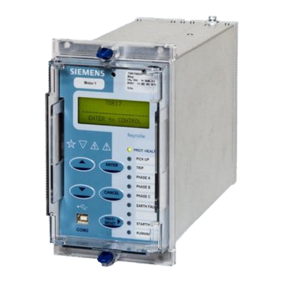
Siemens 7SR17 Rho Motor Protection Relay Manuals
Manuals and User Guides for Siemens 7SR17 Rho Motor Protection Relay. We have
1
Siemens 7SR17 Rho Motor Protection Relay manual available for free PDF download: Manual
Siemens 7SR17 Rho Manual (344 pages)
Motor Protection Relay
Brand:
Siemens
| Category:
Relays
| Size: 3.56 MB
Table of Contents
Table of Contents
7
Section 1: Introduction
13
Table 1-1 Ordering Information - 7SR17 Rho Motor Protection
14
Figure 1-1-1 Functional Diagram of 7SR1702/3 Relay
15
Figure 1-1-2 Functional Diagram of 7SR1705/6 Relay
15
Figure 1-1-3 Connections Diagram for 7SR1702/3 Relay
16
Figure 1-1-4 Connections Diagram for 7SR1705/6 Relay
17
Section 2: Hardware Description
18
General
18
Case
18
Figure 2-1 Rear View of Relay
18
Table 2-1 Summary of 7SR17 Rho Relay Configurations
18
Front Cover
19
Power Supply Unit (PSU)
19
Operator Interface/ Fascia
19
Figure 2-2 7SR17 in E4 Case
19
Current Inputs
21
Voltage Inputs
21
Binary Inputs
22
Figure 2-3 Binary Input Logic
22
Binary Outputs (Output Relays)
23
Figure 2-4 Binary Output Logic
24
Virtual Input/Outputs
25
Self Monitoring
25
Figure 2-5 Start-Up Counter Meter
25
Figure 2-6 Unexpected Restarts Lockout Text
26
Figure 2-7 Start-Up Events
26
Protection Healthy/Defective
27
Figure 2-8 7SR17 Menu Structure
28
Section 3: Protection Functions
29
Thermal Protection
29
Figure 3.1-1 Thermal Overload Heating and Cooling Characteristic
29
Table 3-1 Application of Thermal Time Constants
29
Thermal Protection: Overload (49)
31
Figure 3-2 Logic Diagram: Motor Thermal Overload Protection (49)
32
Figure 3.1-3 Application of Thermal Overload Time Constants
33
Thermal Protection: Stall Protection (14)
35
Figure 3-4 Stall Protection (14)
35
Thermal Protection: Start Protection (48, 66)
36
Figure 3-5 Number of Starts Protection (66)
36
Figure 3-6 Start Time Supervision (48)
37
Thermal Protection: Phase Unbalance (46)
38
Figure 3-7 Inverse Time Characteristic for Unbalance Protection
38
Figure 3-8 Logic Diagram : NPS Phase Unbalance (46NPS)
39
Figure 3-9 Logic Diagram: Phase Difference Phase Unbalance (46PD)
40
Current Protection: Undercurrent (37)
41
Figure 3-10 Logic Diagram: Undercurrent Detector (37)
41
Current Protection: Phase Overcurrent (67, 51, 50)
42
Directional Control of Overcurrent Protection (67)
42
Overcurrent Protection (50)
43
Figure 3-11 Logic Diagram: Instantaneous Over-Current Element
43
Time Delayed Overcurrent Protection (51)
44
Figure 3-12 Logic Diagram: Time Delayed Overcurrent Element
45
Current Protection: Measured Earth Fault (50/51G)
46
Directional Control of Measured Earth Fault Protection (67G) - 7SR1705/6
46
Figure 3-13 Logic Diagram: Measured Directional Earth Fault Protection
46
Measured Earth Fault Protection (50G)
47
Figure 3-14 Logic Diagram: Measured Instantaneous Earth-Fault Element
47
Time Delayed Measured Earth Fault Protection (51G)
48
Figure 3-15 Logic Diagram: Measured Time Delayed Earth-Fault Element
48
Current Protection: Derived Earth Fault (50/51N)
49
Directional Control of Derived Earth Fault Protection (67N) - 7SR1705/6
49
Figure 3-16 Logic Diagram: Derived Directional Earth Fault Element
49
Derived Earth Fault Protection (50N)
50
Figure 3-17 Logic Diagram: Derived Instantaneous Earth Fault Element
50
Time Delayed Derived Earth Fault Protection (51N)
51
Figure 3-18 Logic Diagram: Derived Time Delayed Earth Fault Element
51
Current Protection: High Impedance Restricted Earth Fault (87REF)
52
Figure 3-19 Logic Diagram: High Impedance REF (87REF)
52
Voltage Protection: Under/Over Voltage - 7SR1705/6
53
Phase Under/Over Voltage (27/59)
53
Figure 3-20 Logic Diagram: Under/Over Voltage Elements (27/59)
53
Voltage Protection: NPS Overvoltage (47) - 7SR1705/6
54
Figure 3-21 Logic Diagram: NPS Overvoltage Protection (47)
54
Voltage Protection: Under/Over Frequency (81) - 7SR1705/6
55
Figure 3-22 Logic Diagram: Under/Over Frequency Detector (81)
55
Power Protection - 7SR1705/6
56
Power Protection - 32
56
Figure 3-23 Logic Diagram: Power Protection (32)
56
Sensitive Power Protection - 32S
57
Figure 3-24 Logic Diagram: Sensitive Power Protection (32S)
57
Power Factor - 55
58
Figure 3-25 Logic Diagram: Power Factor (55)
58
Section 4: Supervision Functions
59
Break Capacity Limit (50BCL)
59
Figure 4-1 Logic Diagram: Breaking Capacity Limit (50BCL)
59
Anti-Backspin (81B)
60
Figure 4-2 Logic Diagram: Anti-Backspin Protection (81B)
60
Phase Reversal (46 PH REV)
61
Figure 4-3 Logic Diagram: Phase Reversal Detection (46 PH REV)
61
Resistance Temperature Detector Inputs (Rtds)
62
Figure 4-4 Logic Diagram: Temperature Inputs
62
CT Supervision (60CTS)
63
60Cts - 7Sr1702/3
63
Figure 4-5 Logic Diagram: CT Supervision Function - Current Inputs Only
63
60Cts - 7Sr1705/6
64
Figure 4-6 Logic Diagram: CT Supervision Function - Current and Voltage Inputs
64
Table 4-1 Determination of CT Failure
64
Voltage Transformer Supervision (60VTS) - 7SR1705/6
65
Table 4-2 Determination of VT Failure Using NPS Quantities (1 or 2 Phases)
65
Table 4-3 Determination of VT Failure (3 Phases)
65
Figure 4-7 Logic Diagram: VT Supervision Function (60VTS)
66
Figure 4-8 Logic Diagram: Trip Circuit Supervision Feature (74TCS)
67
Figure 4-9 Logic Diagram: Close Circuit Supervision Feature (74TCS)
67
Figure 4-10 Logic Diagram: Circuit Breaker Fail Protection (50BF)
68
Figure 5-1 Logic Diagram: Circuit Breaker Status
70
Figure 5-2 Logic Diagram: Motor Control
71
Figure 5-3 Sequence Diagram: Quick Logic PU/DO Timers (Counter Reset Mode Off)
72
Figure 6-1 Energy Direction Convention
77
Section 1: Introduction
87
Relay Menus and Display
87
Operation Guide
89
User Interface Operation
89
Setting Mode
91
Instruments Mode
92
Instrument
92
Description
92
Fault Data Mode
99
Section 2: Setting & Configuring the Relay Using Reydisp Evolution
100
Physical Connection
100
Front USB Connection
100
Rear RS485 Connection
100
Configuring Relay Data Communication
101
Connecting to the Relay for Setting Via Reydisp Evolution
102
Connecting to the Relay for Setting Via Reydisp Manager
102
Configuring the User Texts Using Reydisp Language Editor
103
Section 1: Common Functions
111
CE Conformity
111
Reference
111
Dimensions
111
Weights
111
Energising Quantities
112
Auxiliary Power Supply
112
AC Analogue Current
113
AC Analogue Voltage
114
Binary (Digital) Outputs
114
Binary (Digital) Inputs
115
Functional Performance
117
Instrumentation
117
Data Communication
117
Real Time Clock
117
Environmental Performance
118
General
118
Emissions
119
Immunity
120
Mechanical
122
Section 2: Protection Functions
123
Stall
123
Reference
123
Operate and Reset Level
123
Operate and Reset Time
123
27/59 Phase Under/Over Voltage
124
Reference
124
Operate and Reset Level
124
Operate and Reset Time
124
Power
125
Reference
125
Operate and Reset Level
125
Operate and Reset Time
125
Operate Threshold
125
Sensitive Power
126
Reference
126
Operate and Reset Level
126
Operate and Reset Time
126
Operate Threshold
126
Undercurrent
127
Reference
127
Operate and Reset Level
127
Operate and Reset Time
127
Phase Unbalance Protection
128
Reference
128
Operate and Reset Level
128
Operate and Reset Time
128
Negative Phase Sequence Voltage
130
Reference
130
Operate and Reset Level
130
Operate and Reset Time
130
Thermal Overload (Rotating Plant)
131
Reference
131
Operate and Reset Level
131
Operate and Reset Time
131
Overcurrent
133
Reference
133
Operate and Reset Level
133
Operate and Reset Time
133
Measured Earth Fault
134
Reference
134
Operate and Reset Level
134
Operate and Reset Time
134
Derived Earth Fault
135
Reference
135
Operate and Reset Level
135
Operate and Reset Time
135
Time Delayed Overcurrent
136
Reference
136
Operate and Reset Level
136
Operate and Reset Time
137
Time Delayed Measured Earth Fault
138
Reference
138
Operate and Reset Level
138
Operate and Reset Time
139
Time Delayed Derived Earth Fault
140
Reference
140
Operate and Reset Level
140
Operate and Reset Time
142
Power Factor
142
Reference
142
Operate and Reset Level
142
Operate Threshold
142
Under/Over Frequency
143
Reference
143
Operate and Reset Level
143
Operate and Reset Time
143
87REF Restricted Earth Fault Protection
144
Reference
144
Operate and Reset Level
144
Operate and Reset Time
144
Section 3: Supervision Functions
145
46PH REV Phase Reversal
145
Reference
145
Operate and Reset Level
145
Operate and Reset Time
145
50BCL Break Capacity Limit
146
Reference
146
Operate and Reset Level
146
Operate and Reset Time
146
50BF & 50BF-I4 Circuit Breaker Fail
147
Reference
147
Operate and Reset Level
147
Operate and Reset Time
147
60CTS & CTS-I Current Transformer Supervision
148
Reference
148
Current & Voltage Threshold
148
Operate and Reset Time
148
60VTS Voltage Transformer Supervision
149
Reference
149
Operate and Reset Level
149
Introduction
155
Physical Connection
156
Introduction
156
USB Interface (COM2)
157
RS485 Interface (COM1)
158
IEC 60870-5-103 Definitions
160
Introduction
160
Cause of Transmission
161
Application Service Data Unit (ASDU) Type
162
Point List
163
Event Function (FUN) & Information (INF) Numbers
163
Measurands
170
Disturbance Recorder Actual Channel (ACC) Numbers
171
MODBUS Definitions
172
Introduction
172
Fp_32Bits_3Dp
174
Uint32
174
Uint16
174
Event
175
Eventcount
176
Str32 & Str64
177
Bitstring
177
Point List
178
Coils (Read Write Binary Values)
178
Inputs (Read Only Binary Values)
178
Input Registers (Read Only Registers)
183
Holding Registers (Read Write Registers)
187
DNP3 Definitions
188
Device Profile
188
Implementation Table
191
Point List
198
Counters
209
Analog Inputs
210
Additional Settings
215
Not Applicable
216
Section 1: Installation
231
Packaging
231
Unpacking, Storage and Handling
231
Recommended Mounting Position
231
Wiring
231
Earthing
231
Ancillary Equipment
232
Disposal
232
Section 2: Equipment Operating Conditions
233
Current Transformer Circuits
233
External Resistors
233
Front Cover
233
Section 3: Dimensions and Panel Fixings
234
Relay Dimensions and Weight
234
Fixings
235
Crimps
235
Panel Fixings
235
Section 4: Rear Terminal Drawings
236
E4 Case
236
Section 5: Connection/Wiring/Diagrams
238
Wiring Diagram: 7SR1702/3 Relay
238
Voltage Transformer Configurations
242
Typical Connections
243
Section 6: Data Comms Connections
244
RS485 Connection
244
Section 1: Common Functions
251
Overview
251
Before Testing
251
Safety
251
Sequence of Tests
251
Test Equipment
252
Use of PC to Facilitate Testing
252
Precautions
252
Applying Settings
252
Relay Functionality
253
Tests
254
Inspection
254
Secondary Injection Tests
254
Primary Injection Tests
254
Putting into Service
254
AC Analogue Energising Quantities
255
Binary Inputs
255
Binary Outputs
256
Relay Case Shorting Contacts
256
Section 2: Protection Functions
257
Thermal Overload (49)
259
Stall Protection (14)
261
Start Protection (48/66)
263
Phase Unbalance Protection (46)
264
Negative Phase Sequence
265
Magnitude Difference
265
Element Blocking
265
Undercurrent (37)
266
Phase Directional Polarity Check
268
Out of 3 Logic
269
Phase Overcurrent (67/50, 67/51)
270
Definite Time Overcurrent (50)
270
Directional Earth Fault Polarity Check (67N)
273
Derived Earth Fault (67/50N, 67/51N)
274
Directional Polarity
275
Definite Time Overcurrent (50N)
275
Inverse Time Overcurrent (51N)
275
Measured Earth Fault (67/50G, 67/51G)
278
Directional Polarity
279
Definite Time Overcurrent (67/50G)
279
Inverse Time Overcurrent (67/51G)
279
Restricted Earth Fault (87REF)
282
Over/Under Voltage
284
Phase Under/Over Voltage (27/59)
284
Undervoltage Guard (27/59UVG)
285
NPS Overvoltage (47)
286
Under/Over Frequency (81)
287
Power Protection
289
Power (32)
289
Sensitive Power (32S)
291
Power Factor (55)
292
Section 3: Supervision Functions
293
Break Capacity Limit (50BCL)
293
Anti-Backspin (81B)
293
Phase Reversal
294
Temperature Inputs
295
Current Transformer Supervision (60CTS)
296
7Sr1703
296
7Sr1706
297
Voltage Transformer Supervision (60VTS)
298
Or 2 Phase VT Fail
298
Phase VT Fail
299
CB Fail (50BF)
300
Element Blocking
301
Trip/Close Circuit Supervision (74T/CCS)
302
Section 4: Control & Logic Functions
303
Quick Logic
303
Section 5: Testing and Maintenance
304
Periodic Tests
304
Maintenance
304
Troubleshooting
304
Section 1: Introduction
311
Plant Design - Motors
311
Section 2: Protection Functions
312
Stall Protection (14)
318
Start Protection (66)
320
Phase Unbalance Protection (46)
320
Setting Example - Thermal Protection
321
Overcurrent (50-N, 51-N)
326
Instantaneous Overcurrent (50-N)
326
Time Delayed Overcurrent (51-N)
326
Earth-Fault Protection (50G/50N)
327
High Impedance Restricted Earth Fault Protection (87REF)
328
Voltage Protection (27/59)
329
Under Voltage
329
Over Voltage
329
Frequency (81)
329
Power Protection
330
Power (32)
330
Sensitive Power (32S)
330
Power Factor (55)
330
Section 3: Current Transformer (CT) Requirements
331
CT Ratio
331
Thermal and Overcurrent Protection Cts
331
Earth Fault Protection Cts
331
Sensitive Power (32S)
331
Section 4: Supervision and Monitoring Functions
332
Breaking Capacity Limit (50BCL)
332
Backspin Protection (81B)
332
Current Transformer Supervision (60CTS)
332
Voltage Transformer Supervision (60VTS)
333
Trip-Circuit Supervision (74TCS)
334
Trip Circuit Supervision Connections
334
Close Circuit Supervision Connections
336
Circuit-Breaker Fail (50BF)
337
Section 5: Control & Logic Functions
338
User Defined Logic
338
Undervoltage Auto Restart (Restoration of Supply)
338
Motor Start/Stop
338
Section 6: Application Examples
339
Function and Connection Diagrams
339
Section 7: Common Functions
340
Binary Inputs
340
Advertisement
Advertisement
Related Products
Siemens Argus 7SR11
Siemens Argus 7SR12
Siemens 7SR18 Solkor
Siemens 7SR105 Rho
Siemens 7SR10 Argus Series
Siemens 7SR1003 Argus
Siemens 7SR1002 Argus
Siemens 7SR1004 Argus
Siemens 7SR158 Argus
Siemens 7SR242 Duobias
Siemens Categories
Industrial Equipment
Controller
Control Unit
Oven
Washer
More Siemens Manuals
Login
Sign In
OR
Sign in with Facebook
Sign in with Google
Upload manual
Upload from disk
Upload from URL