Sign In
Upload
Manuals
Brands
Siemens Manuals
Controller
RVP540
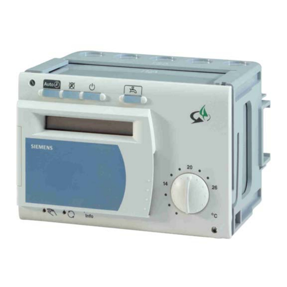
Siemens RVP540 Energy Manager Controller Manuals
Manuals and User Guides for Siemens RVP540 Energy Manager Controller. We have
2
Siemens RVP540 Energy Manager Controller manuals available for free PDF download: Basic Documentation, Installation Instructions Manual
Siemens RVP540 Basic Documentation (348 pages)
Heat Energy Manager
Brand:
Siemens
| Category:
Controller
| Size: 2.17 MB
Table of Contents
Table of Contents
3
1 Summary
17
Brief Description
17
Features
17
Range of Products
19
Field of Use
20
Product Liability
20
Environmental Compatibility
20
2 Handling
21
Installation
21
Mounting Location
21
Mounting Methods
21
Mounting Procedure (Base Mounting)
22
Electrical Installation
24
Regulations for Installation
24
Installation Procedure
24
Commissioning
27
Functional Checks
27
Operation
28
Operating Elements
28
Operating Procedure
29
Parameter Settings for the Enduser
30
Overview of Enduser Parameters
31
Parameter Settings for the Heating Engineer
33
Overview of Heating Engineer Parameters
34
Parameter Settings for the Expert
49
Overview of EXP Parameters
50
Operational Faults
53
3 Description of the Enduser Settings
55
User Interface
55
Heating Circuit Operating Modes
55
Operating Mode of D.h.w. Heating
57
Manual D.h.w. Push
57
Nominal Room Temperature Setpoint
58
Temperature Adjustment Via the Room Unit
59
Manual Operation
59
Green Mode
61
Info Button
62
Setting the Clock
63
Time of Day
63
Weekday
63
Date (Day / Month) and Year
63
Time Switch Program for Space Heating
64
Preselection of Weekday
64
Switching Times
65
Free Time Switch Program
66
Preselection of Weekday
66
Switching Times
66
Time Switch Program for D.h.w. Heating
67
Preselection of Weekday
67
Switching Times
68
Values
69
Nominal D.h.w. Temperature Setpoint
69
Heating Circuit Values
70
Reduced Room Temperature Setpoint (Trrw)
70
Frost Protection Setpoint of the Room Temperature (Trfw)
71
Summer / Winter Changeover Temperature of the Heating Circuit
71
Heating Curve Slope
73
Actual Value of the Room Temperature
73
General
74
Actual Value of the Outside Temperature
74
Resetting the Enduser Parameters
74
Resetting the Heating Circuit and D.h.w. Time Switch Programs
74
Holiday Program
75
Preselection of Holiday Periods
76
Start and End of the Holiday Period
76
General / Service
76
Indication of Faults
76
Chimney Sweep
79
Solar Collectors
80
24-Hour Yield of Solar Energy
80
Total Yield of Solar Energy
80
Acknowledgement of Heat Pump Error Messages 135 and 137
80
4 Description of the Heating Engineer Settings
81
General / Service
81
Basic Diagrams
81
Selection of the Basic Diagram Number
81
Configuration
82
Partial Diagrams
82
Selection of Partial Diagram "Oil- / Gas-Fired Boiler
82
Selection of Partial Diagram "Solar Collectors
83
Selection of Partial Diagram "Wood-Fired Boiler
84
Selection of Partial Diagram "Heat Pump
84
Display of Partial Diagram "Buffer Storage Tank
85
Display of Partial Diagram "D.h.w. Storage Tank
85
Display of Partial Diagram "Combi Storage Tank
86
Selection of Partial Diagram "Heating Circuit
86
Hiding Sensors that Are Not Required
87
Source Outside Sensor B9
87
Reduction First D.h.w. Storage Tank Temperature Sensor B3
87
Reduction Second D.h.w. Storage Tank Temperature Sensor B31
88
Reduction Second Buffer Storage Tank Temperature Sensor B41
88
Reduction Return Temperature Sensor B72 of the Wood-Fired Boiler
88
Reduction Heat Pump Flow Temperature Sensor B21
89
Reduction Heat Pump Return Temperature Sensor B71
89
Reduction Water / Brine Temperature Sensor B11
89
Auxiliary Functions
90
Return Diversion Y15 / Y¯ 15 / B73 (Zufu1)
90
Partial Storage Tank Y14 / Y¯14 / B43 (Zufu2)
92
Storage Tank Transfer Pump Q11 (Zufu3)
94
Circulating Pump Q4 (Zufu4)
95
Additional Pump Q17 for Heat Pump Stage 2 (Zufu5)
96
System Pump Q14 (Zufu6)
97
Pump H1 Q15 (Zufu7)
98
Alarm Output K10 (Zufu8)
99
Output "Overtemperature Protection K11 / K¯11" (Zufu9)
100
Relay K17 for the Flue Gas Temperature Function (Zufu10)
101
Flue Gas Temperature Sensor B8 (Zufu10)
102
Third Buffer Storage Tank Temperature Sensor B42 (Zufu11)
103
Common Flow Temperature Sensor B10 (Zufu12)
104
Solar Flow Temperature Sensor B62 (Zufu13)
105
Solar Flow Temperature Sensor B63 for Yield Measurement (Zufu14)
106
Solar Return Temperature Sensor B64 for Yield Measurement (Zufu14)
107
Solar Heat Exchanger Diverting Valve K¯8 (Zufu15)
107
Solar Diverting Valve K¯9 (Zufu16)
108
Output (K13) for the Free Time Switch Program (Zufu23)
109
Electric Immersion Heater Buffer Storage Tank K16 (Zufu24)
110
Electric Immersion Heater K6 for the D.h.w. Storage Tank (Zufu25)
112
Diverting Valve Q¯3 (Zufu26)
113
Heat Generation Lock Y4 / Y¯4 (Zufu27)
114
Solar Swimming Pool Heating K18 / K¯18 / B13 (Zufu28)
116
Miscellaneous
121
Heating with Charging Pump or Diverting Valve Q3
121
Setpoint and Time Switch Program for D.h.w. Heating with a BMU
122
Function of System Pump Q14
122
General
123
Configuration Diagnosis
123
Display of Relay Terminal Assignment
123
Display of Sensor Terminal Assignment
124
Display of Configuration Errors
125
Display of Diagram Identification Numbers (Parts 1, 2, 3 and 4)
127
Terminal Test
128
Output Test
128
Input Test
129
Display of PPS Communication
130
Setpoint / Actual Value of the Common Flow
131
Display of the Common Flow Temperature Setpoint
131
Actual Value of the Common Flow Temperature
132
Flue Gas Temperature
132
Actual Value B8 of the Flue Gas Temperature
132
Display of Maximum Value of Flue Gas Temperature B8
132
Maximum Limitation of the Flue Gas Temperature
133
Switch-On Temperature Flue Gas Temperature Sensor Function (Zufu10)133
133
Oil- / Gas-Fired Boiler
135
Setpoints / Actual Values
135
Display of the Boiler Temperature Setpoint (Tkw)
135
Actual Value B2 / PPS (Tkx) of the Boiler Temperature
135
Setpoint of Minimum Limitation of the Return Temperature
135
Actual Value of Return Temperature B7
136
Burner Hours Run of Stage 1 (K4 / PPS)
136
Burner Hours Run of Stage 2 (K5)
137
Number of Burner Starts of Stage 1 (K4 / PPS)
137
Number of Burner Starts of Stage 2 (K5)
137
Functions
138
Minimum Limitation of the Boiler Temperature (Tkmin)
138
Frost Protection for the Plant with the Boiler Pump
139
Diagnosis
139
Display of BMU Error Code
139
Functional Test of Oil- / Gas-Fired Boiler
140
Solar Collectors
141
Setpoints / Actual Values
141
Actual Value of Solar Collector Sensors B6 and B61
141
Actual Value of Collector Flow Temperature B62
142
Maximum Values B6 and B61 of the Collector Temperature
142
Temperature Differentials Collector / Heat Exchanger
143
Temperature Differentials Collector / Swimming Pool
145
Hours Run Counter
145
Hours Run of Collector Pumps Q5 and Q16
145
Hours Run of Pump K12 / Diverting Valve K8
146
Hours Run of Swimming Pool Heating K18
146
Solar Swimming Pool Heating
147
Swimming Pool Setpoint Temperature
147
Actual Value of Swimming Pool Temperature B13
147
Temperature Differential Swimming Pool on
147
Temperature Differential Swimming Pool off
148
Maximum Swimming Pool Charging Temperature
148
Heat Exchanger Pump Operation for Swimming Pool
148
Measured Value Correction Swimming Pool Sensor B13
149
Functions
150
Selection of the Type of Collector Sensors B6 and B61
150
Measured Value Correction Collector Sensors B6 / B61 / B62
150
Heat Exchanger Pump Operation for Partial Diagram Sol 5
151
Temperature Differential on Heat Exchanger
152
Temperature Differential off Heat Exchanger
153
Priority with 2 Heat Exchangers
154
Solar Yield Measurement
156
Type of Antifreeze Agent Added
157
Concentration of Antifreeze Agent
157
Pulse Value Flow Meter
158
Volumetric Flow Solar Pump
158
Selection of Type of Sensor B63 and B64 for Solar Yield Measurement
159
Actual Value of Solar Flow Temperature B63
159
Actual Value of Solar Return Temperature B64
159
Speed-Controlled Solar Pump
160
Functioning
160
Display of Speed of the Solar Pump Q5 / K9
161
Minimum Speed of the Solar Pump
161
Maximum Speed of the Solar Pump
162
Diagnosis
162
Functional Test Solar
162
Wood-Fired Boiler
163
Setpoints / Actual Values
163
Display of the Boiler Temperature Setpoint
163
Display of Actual Value of Boiler Temperature B22
163
Display of the Return Temperature Setpoint
163
Display of Actual Value of Return Temperature B72
163
Hours Run Counter
164
Operating Hours of Pump of the Wood-Fired Boiler
164
Operating Hours of Wood-Fired Boiler (K3)
164
Number of Releases of the Wood-Fired Boiler (K3)
164
Functions
165
Minimum Temperature Differential of the Wood-Fired Boiler
165
Minimum Temperature of the Wood-Fired Boiler for Release of the Pump
166
Switching Differential of "Minimum Temperature of the Wood-Fired Boiler for Release of the Pump
167
Pump Overrun Time
167
Strategy for the Wood-Fired Boiler
168
Generation of Heat Demand (Setting 1)
169
Storage Tank Priority
169
Wood-Fired Boiler Locks Other Heat Sources
170
Frost Protection for the Plant with the Pump of the Wood-Fired Boiler
170
Residual Heat Function
171
Maximum Duration of the Residual Heat Function
171
Residual Heat Function Performed Once / Several Times
172
Residual Heat Function Directly for the Consumers
173
Speed-Controlled Pump of Wood-Fired Boiler
174
Display of Speed of Pump Q10 of the Wood-Fired Boiler
174
Minimum Speed of Pump of the Wood-Fired Boiler
174
Maximum Speed of Pump of the Wood-Fired Boiler
174
Diagnosis
175
Functional Test of the Wood-Fired Boiler
175
Heat Pump
175
Setpoints / Actual Values
175
Display of Heat Pump Flow Temperature Setpoint
175
Actual Value of the Heat Pump Flow Temperature B21
176
Display of Heat Pump Return Temperature Setpoint
176
Display of Actual Value of Heat Pump Return Temperature B71
176
Actual Value of Water / Brine Flow Temperature B11
176
Hours Run Counter
177
Operating Hours Heat Pump Stage 1 (K1)
177
Operating Hours Heat Pump Stage 2 (K2)
177
Number of Starts of Heat Pump Stage 1 (K1)
178
Number of Starts of Heat Pump Stage 2 (K2)
178
Functions
179
Control Sensors for the Heat Pump
179
Heat Pump Switching Differential on
180
Heat Pump Switching Differential off
180
Flow / Return Temperature Differential at -10 °C
181
Compensation of Mixing Valve Boost
182
Frost Protection for the Plant Acting on the Heat Pump Circulator
182
Additional Pump Kick for Water / Brine Pump
183
Control of the Heat Pump Circulators
183
Diagnosis
184
Functional Test of the Heat Pump
184
Buffer Storage Tank
185
Setpoints / Actual Values
185
Actual Values of Buffer Storage Tank Temperature Sensors
185
And B43
185
Maximum Value of Buffer Storage Tank Sensor B4
186
Display of Actual Value of Return Temperature B73
186
Display of Setpoint of the Buffer Storage Tank Temperature
186
Functions
187
Buffer Storage Tank Charging with the Wood-Fired Boiler
187
Minimum Buffer Storage Tank Temperature Level When Charging with the Collectors (Tpmin)
188
Maximum Buffer Storage Tank Charging Temperature
189
Automatic Heat Generation Lock
189
ΔT Differential between Buffer Storage Tank Temperature and Heat Demand from the Heating Circuit
190
Forced Buffer Storage Tank Charging with Heat Pump
190
Return Diversion
192
Return Diversion Temperature Differential on (Zufu1)
192
Return Diversion Temperature Differential off (Zufu1)
192
Operating Action of the Return Diversion (Zufu1)
193
Storage Tank Sensor for the Return Diversion (Zufu1)
193
Electric Immersion Heater
194
Release Outside Temperature for Electric Immersion Heater in the Buffer Storage Tank
194
Selection of Control Sensor for Electric Immersion Heater in the Buffer Storage Tank
194
Buffer Storage Tank Overtemperature
195
Functioning
195
Difference between the Maximum Storage Tank Temperature (MSP) and the Buffer Storage Tank Safety Temperature
196
Hysteresis for Buffer Storage Tank Cooling Function with Priority 1
196
Priority of Buffer Storage Tank Cooling with the Transfer Pump
197
Priority of Buffer Storage Tank Cooling with the Collector Pump
197
Priority of Buffer Storage Tank Cooling with the Heat Source Pump
198
Priority of Buffer Storage Tank Cooling with Overtemperature Protection Output K11
198
Priority of Buffer Storage Tank Cooling through Delivery of Heat for Space
199
Heating 199 D.h.w. Storage Tank
200
Functions
200
Heating with Electric Immersion Heater K6
200
Recharge Control of the D.h.w. Storage Tank
201
Minimum D.h.w. Storage Tank Temperature Level When Charging with the Collector (Tbmin)
202
Maximum D.h.w. Storage Tank Charging Temperature
203
Heat Transfer to the D.h.w. Storage Tank
203
Functioning
203
Heat Transfer with the D.h.w. Sensor
204
Automatic Heat Transfer from the Buffer to the D.h.w. Storage Tank
204
Heat Transfer Strategy Summer / Winter
204
Heat Transfer Temperature Differential on
205
Heat Transfer Temperature Differential off
205
Overtemperature Protection D.h.w. Storage Tank
206
Functioning
206
Difference between the Maximum Storage Tank Temperature (MSB) and the D.h.w. Storage Tank Safety Temperature
207
Hysteresis for the D.h.w. Cooling Function with Priority 1
207
Priority of D.h.w. Storage Tank Cooling with the Heat Transfer Pump
208
Priority of D.h.w. Storage Tank Cooling with the Collector Pump
208
Priority of D.h.w. Storage Tank Cooling with Overtemperature Protection Output K11
209
Diagnosis
209
Functional Test of the D.h.w. Storage Tank
209
Combi Storage Tanks
209
B4 Delivers the Temperature Signal for the B31 Functionality
209
Bivalent Operation
210
Heat Source Sequence
210
Lead Heat Source
210
Delayed Switching on of Lag Heat Source
211
Release Integral for the Lag Heat Source
211
Reset Integral of the Lag Heat Source
211
Release Depending on the Outside Temperature
212
Release of Heat Pump above the Outside Temperature Threshold
214
Release of Wood-Fired Boiler below the Outside Temperature Threshold.214
214
Heating
215
Heat Source Strategy for D.h.w. Heating
215
Heating Circuit / Space Heating
216
Setpoints / Actual Values
216
Displaying the Nominal Room Temperature Setpoint
216
Display of Room Temperature Setpoint Trw
217
Heating Circuit Flow Temperature Setpoint Tvw
217
Actual Value of the Heating Circuit Flow Temperature Tvx (B1)
217
Attenuated Outside Temperature Taxged
218
Composite Outside Temperature Taxgem
219
Measured Value Correction Outside Sensor B9
220
Functions
220
Parallel Displacement of the Heating Curve
220
Room Influence
221
Switching Differential of the Room Temperature (SDR)
222
Minimum Limitation of the Flow Temperature Setpoint (Tvmin)
223
Maximum Limitation of the Flow Temperature Setpoint (Tvmax)
224
Type of Building Construction
224
Adaption of the Heating Curve
225
Maximum Forward Shift of Optimum Start Control
227
Without Room Temperature Sensor
227
With Room Temperature Sensor
228
Maximum Forward Shift of Optimum Stop Control
228
Locking Signal Gain Heating Circuit
229
Frost Protection for the Plant with the Heating Circuit Pump
229
Outside Temperature for Start and End of Lift of the Reduced Room Temperature Setpoint
230
Floor Curing
231
Temperature Profile
231
Activating the Function
232
Function
232
Display
232
Aborting the Function
232
Floor Curing Data
233
Speed-Controlled Pump
233
Display of Speed of Heating Circuit Pump Q2
233
Minimum Speed of the Heating Circuit Pump
233
Maximum Speed of the Heating Circuit Pump
233
Speed Reduction of the Heating Circuit Pump
234
Diagnosis
234
Functional Test of the Heating Circuit
234
D.h.w
235
Setpoints / Actual Values
235
Display of the D.h.w Temperature Setpoint Tbww
235
Actual Values of D.h.w. Temperatures B3/BMU, B31, B32 and B33
236
Maximum Values of D.h.w. Temperatures B3 / B32
236
Functions
237
Reduced Setpoint of D.h.w. Temperature TBWR
237
Release of D.h.w. Heating
238
24-Hour Operation Setting 0
238
Operation According to the Heating Program with Forward Shift, Setting 1238 4.224.3 Operation According to the D.h.w. Time Switch Program Setting 2
239
Program Selection Circulating Pump
239
Assignment of D.h.w. Heating
240
Number of D.h.w. Charging Cycles
241
Once Per Day with a Forward Shift of 2.5 Hours Setting 0
241
Several Times Per Day with a Forward Shift of 1 Hour Setting 1
241
Type of D.h.w. Demand
242
Boost of the Flow Temperature Setpoint for D.h.w
243
Priority
244
Shifting Priority
244
Priority When Charging with the Buffer Storage Tank
246
Automatic D.h.w. Push
247
Charging Time Limitation
248
Changeover to D.h.w. Heating with Electric Immersion Heater
248
Legionella Function
249
Periodicity of the Legionella Function
249
Legionella Function Strategy
250
Setpoint of the Legionella Function
251
Time for the Legionella Function
251
Dwelling Time at Legionella Function Setpoint
251
Circulating Pump Operation During the Legionella Function
252
General Functions
253
Effect of the Green Button
253
Frost Protection for the Plant with the System Pump
253
Central Setpoint Compensation
254
LPB / System
255
LPB Device Address
255
LPB Segment Address
256
LPB Power Supply
256
Display of LPB Power Supply
257
Range of Action of Central Changeover
257
Automatic Summer / Winter Changeover
258
Central Standby Switch
258
Outside Temperature Source
259
Clock
260
Clock Mode
260
Winter- / Summertime Changeover
261
Summer- / Wintertime Changeover
261
Input H1
262
Function Selection Input H1
262
Changeover of Operating Mode (Remote Telephone Switch) Setting 1 / 2263 4.255.2 Minimum Setpoint of the Flow Temperature, Contact H1 Setting 3
265
Heat Generation Lock Oil / Gas or Heat Pump Setting 4 or 11
265
Heat Demand Setting 5
265
Minimum Setpoint of the Flow Temperature, Contact H1 (Tvhw)
266
Maximum Value of Heat Demand DC 0
267
Operating Action of the Contact Connected to H1
267
Input E1
268
Display of Hours Run, Input E1
268
Display of Number of Starts, Input E1
268
Function Selection Input E1
268
Operating Action of Voltage Signal at Input E1
270
Output P1 (PWM)
270
Function Selection P1
270
PWM Signal Logic P1
271
Display of PWM Output P1
272
Output Test PWM Signal P1
272
Output Ux (DC 0
272
Function Selection Output Ux
272
Maximum Value of Heat Demand Ux
274
Voltage Output Signal Logic Ux
275
Displaying Voltage Output Ux
275
Output Test Voltage Output Ux
275
Reset
276
Resetting the Heating Engineer Parameters
276
5 Description of the EXP Settings
277
EXP General
277
General Frost Protection for the Plant
277
Frost Protection for the Plant
278
Oil- / Gas-Fired Boiler EXP
279
Minimum Limitation of the Boiler Temperature Setpoint EXP
279
Exp )
279
Maximum Limitation of the Boiler Temperature Setpoint (Tkmax)
279
Switching Differential of the Boiler Temperature (SDK)
279
Minimum Limitation of the Burner Running Time
281
Release Integral of Burner Stage 2
282
Reset Integral of Burner Stage 2
283
Pump Overrun Time
284
Operating Mode of the Boiler
285
Protective Boiler Startup
286
Impact on 2-Position Loads
286
Impact on Modulating Loads
287
Temperature-Time Integral
287
Control of the Boiler Pump
288
Minimum Limitation of the Return Temperature
289
Minimum Limitation of the Boiler Return Temperature EXP
289
Maintained Boiler Return Temperature with Impact on the Consumers
289
Switching Differential of the Bypass Pump (SDBP)
290
Control of the Bypass Pump
291
Parallel with the Burner Setting 0
291
According to the Boiler Return Temperature Setting 1
292
P-Band Minimum Limitation of the Return Temperature Oil / Gas (Xp)
293
Integral Action Time Minimum Limitation of the Return Temperature Oil / Gas (Tn)
293
Actuator Running Time Minimum Limitation of the Return Temperature Oil / Gas
294
Solar Collectors
294
Maximum Limitation of the Collector Temperature
294
Hysteresis for Maximum Limitation of the Collector Temperature
295
Collector Frost Protection Temperature
295
Maximum Storage Tank Charging Time
296
Maximum Waiting Time
297
Changeover / Startup Delay Bypass Valve / Charging Pump K9
297
Protection for the Collector Pump
298
Evaporation Temperature of Heat Conducting Medium
298
Switching Differential to Evaporation Temperature of Heat Conducting Medium
298
Wood-Fired Boilers
299
Protective Startup of Wood-Fired Boilers
299
Minimum Limitation of the Return Temperature of the Wood-Fired Boiler
299
P-Band Minimum Limitation of the Return Temperature of the Wood-Fired Boiler (Xp)
300
Integral Action Time Minimum Limitation of the Return Temperature of the Wood-Fired Boiler (Tn)
300
Actuator Running Time Minimum Limitation of the Return Temperature of the Wood-Fired Boiler
301
Heat Pump
301
Maximum Switch-Off Temperature
301
Minimum Switch-On Temperature
301
Prerun Time of Heat Pump Circulator and Water / Brine Pump
302
Overrun Time of Heat Pump Circulator and Water / Brine Pump
302
Minimum Compressor on Time
302
Minimum Compressor off Time
303
Automatic Switch-On Attempt after Heat Pump Fault 135 and 137
303
Compensation of Running Time-Related Surplus Heat / Heat Deficit
304
Second Heat Pump Stage
305
Locking Time of Heat Pump Stage 2
305
Release Integral Heat Pump Stage 2
305
Reset Integral Heat Pump Stage 2
306
Changeover of Stage Sequence
306
Minimum Water / Brine Temperature
306
Switching Differential of Minimum Water / Brine Temperature
307
Buffer Storage Tank EXP
307
Buffer Storage Tank Safety Temperature
307
Storage Tank EXP
308
Storage Tank Safety Temperature
308
Space Heating EXP
308
Boost of the Flow Temperature Setpoint at the Mixing Valve (UEM)
308
Gain Factor of Room Influence (KORR)
309
Constant for Quick Setback and Optimum Start Control (KON)
310
Boost of Room Temperature Setpoint
311
Control Mode of Actuator
312
Switching Differential of Actuator
312
Overtemperature Protection for the Pump Heating Circuit
313
Heat Gains (Tf)
314
Adaption Sensitivity 1 (ZAF2)
314
Adaption Sensitivity 2 (ZAF2)
315
P-Band of the Heating Circuit (Xp)
316
Integral Action Time of the Heating Circuit (Tn)
316
Actuator Running Time Heating Circuit
317
Exp
317
Maximum Nominal Setpoint of the D.h.w. Temperature (Tbwmax)
317
Switching Differential of the D.h.w. Temperature (SDBW)
318
Discharge Protection When Charging with the Wood-Fired Boiler
319
Discharge Protection When Charging with the Oil- / Gas-Fired Boiler320
320
General / Service EXP
320
Software Version
320
Device Operating Hours
321
Resetting the EXP Parameters
321
Displaying the Version of the Basic Diagram Table
321
6 General Control Processes
322
Generating the Boiler Temperature Setpoint
322
Slave Pointer for the Buffer Storage Tank
323
Setpoint Boost for the Combi Storage Tank (Kosp 1 - 3)
323
Protection against Discharging after D.h.w. Heating
324
Automatic 24-Hour Heating Limit
324
Without Room Influence
324
With Room Influence
325
Quick Setback with Room Temperature Sensor
326
Temperature Differential of Flow / Return Temperature
327
Purpose of the Function
327
Variants
327
Function Description of Variant 2 (According to the Heating Curve)
328
Setting the Parameters at the Time of Commissioning
328
Control of Pumps with no Speed Control
329
Pump Kick / Valve Kick
330
Frost Protection
330
For the BMU (Modulating)
330
For a Single- or 2-Stage Oil- or Gas-Fired Boiler
330
For the Heating Circuit
331
For the D.h.w. Storage Tank
331
For the Buffer Storage Tank
332
7 Dimensions
333
8 Technical Data
334
Advertisement
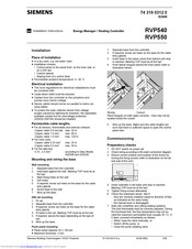
Siemens RVP540 Installation Instructions Manual (28 pages)
Energy Manager / Heating Controller
Brand:
Siemens
| Category:
Controller
| Size: 0.64 MB
Advertisement
Related Products
Siemens RVP36
Siemens RVP550
Siemens RVP360
Siemens RVP201.0
Siemens RVP211.0
Siemens RVP201
Siemens RVP211
Siemens RVP200
Siemens RVP210
Siemens RVA63.242
Siemens Categories
Industrial Equipment
Controller
Control Unit
Oven
Washer
More Siemens Manuals
Login
Sign In
OR
Sign in with Facebook
Sign in with Google
Upload manual
Upload from disk
Upload from URL