Sign In
Upload
Manuals
Brands
Siemens Manuals
Controller
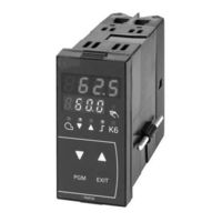
RWF40.001A97
User Manuals: Siemens RWF40.001A97 Controllers
Manuals and User Guides for Siemens RWF40.001A97 Controllers. We have
3
Siemens RWF40.001A97 Controllers manuals available for free PDF download: User Manual, Quick Start Manual
Siemens RWF40.001A97 User Manual (57 pages)
RWF40 Series, Compact Universal Controllers
Brand:
Siemens
| Category:
Controller
| Size: 0.85 MB
Table of Contents
Table of Contents
3
1 Introduction
6
General Notes
6
Description
6
Typographical Conventions
7
Warning Symbols
7
Notification Symbols
7
Presentation
7
2 Type of Unit
8
Type Field
8
3 Installation
9
Installation Site and Climatic Conditions
9
Dimensions
9
Side-By-Side Mounting
10
Mounting in a Panel Cutout
10
Cleaning the Front
11
Removing the Controller Module
11
4 Electrical Connections
12
Installation Notes
12
Block Diagram
13
Assignment of Terminals
14
Galvanic Separation
17
5 Operating Modes
18
Low-Fire Operation
18
High-Fire Operation
18
Modulating Burner, Floating Output
18
Modulating Burner, Analog Output
19
2-Stage Burner, Floating Output
19
2-Stage Burner, Analog Output
20
Safety Shutdown
20
Predefined Setpoint
20
Setpoint Changeover «SP1 / SP2», Analog Setpoint Shift
21
Setpoint Changeover «SP1» / External Setpoint
22
Setpoint «SP1», Analog / Binary Setpoint Shift
23
External Setpoint, Binary Setpoint Shift
24
Weather-Dependent Setpoint Shift
25
Heating Curve Slope
26
Response Threshold «Q
27
Cold Start of Plant
28
6 Operation
29
Basic Display
30
Meaning of the Display and Buttons
30
User Level
31
Changing the Setpoints
31
Manual Operation of a Modulating Burner
33
Manual Operation of a 2-Stage Burner
33
Start Self-Setting
34
Display of the Software Version and of Unit of Actual Value
34
Parameter Level
35
Entering Parameters
35
Configuration Level
35
Changing the Configuration Code
35
7 Parameter Settings
36
8 Configuration
38
C111 Inputs
38
C112 Limit Comparator, Controller Type, Setpoint «SP1», Locking
40
C113 Unit Address, Dimensional Unit, Out-Of-Range
44
SCH Scaling of Standard Signal Range End, Analog Input 1
45
SCL Scaling of Standard Signal Range Start, Analog Input 1
45
Scl2 = 20
45
SCH2 Scaling of Standard Signal Range End, Analog Input 2
46
SPL Lower Setpoint Limit
46
SPH Upper Setpoint Limit
46
OFF1 Actual Value Correction for Analog Input 1
46
OFF2 Actual Value Correction for Analog Input 2
46
OFF3 Actual Value Correction for Analog Input 3
46
Df1 2Nd Order Digital Filter for Analog Input 1
46
Df3 1St Order Digital Filter for Analog Input 3 (Only with RWF40.0X2B97)
46
Ollo Lower Working Range Limit (Only with RWF40.0X2B97)
47
Olhi Upper Working Range Limit (Only with RWF40.0X2B97)
47
Dtt Bus Watchdog Timer for Remote Operation (Only with RWF40.0X2B97)
47
9 Self-Setting Function
48
Self-Setting Function in High-Fire Operation
48
Checking the Controller Parameters
50
10 What to Do if
51
Numbers Are Flashing on the Display
51
11 Technical Data
52
Inputs
52
Analog Input 1 (Actual Value)
52
Analog Input 2 (External Setpoint, Setpoint Shift)
52
Analog Input 3 (Outside Temperature)
53
Binary Input «D1
53
Binary Input «D2
53
Outputs
53
Output 1 (Release of Burner)
53
Output 2, 3 (Floating Output)
53
Output 4 (Limit Comparator)
53
Output 5, Analog Output (Option)
54
Transducer Supply
54
Interface RS-485 (Optional)
54
General Ratings
54
Measuring Accuracy
55
Monitoring of Measuring Circuit
55
Environmental Conditions
55
12 Current Settings
56
Process Data
56
Parameter Level
56
Configuration Level
57
Advertisement
Siemens RWF40.001A97 User Manual (56 pages)
Compact Universal Controller
Brand:
Siemens
| Category:
Controller
| Size: 0.81 MB
Table of Contents
Table of Contents
3
1 Introduction
6
General Notes
6
Description
6
Typographical Conventions
7
Warning Symbols
7
Notification Symbols
7
Presentation
7
2 Type of Unit
8
Type Field
8
3 Installation
9
Installation Site and Climatic Conditions
9
Dimensions
9
Side-By-Side Mounting
10
Mounting in a Panel Cutout
10
Cleaning the Front Panel
11
Removing the Controller Module
11
4 Electrical Connections
12
Installation Notes
12
Block Diagram
13
Assignment of Terminals
14
Galvanic Separation
17
5 Operating Modes
18
Low-Fire Operation
18
High-Fire Operation
18
Modulating Burner, 3-Position Output
18
Modulating Burner, Modulating Output
19
Two-Stage Burner, 3-Position Output
19
Two-Stage Burner, Modulating Output
20
Safety Shutdown
20
Pre-Defined Setpoint
20
Setpoint Changeover "SP1 / SP2", Analog Setpoint Shift
21
Setpoint Changeover "SP1" / External Setpoint
22
Setpoint "SP1", Analog / Binary Setpoint Shift
23
External Setpoint, Binary Setpoint Shift
24
Weather-Dependent Setpoint Shift
25
Heating Curve Slope
26
Response Threshold "Q
27
Cold Start of the Plant
28
6 Operation
29
Basic Display
30
Meaning of the Display and Buttons
30
User Level
31
Changing the Setpoints
31
Manual Operation of a Modulating Burner
33
Manual Operation of a Two-Stage Burner
33
Start Self-Setting
34
Display of the Software Version and Unit of Actual Value
34
Parameter Level
35
Enter Parameters
35
Configuration Level
35
Changing the Configuration Code
35
7 Parameter Settings
36
8 Configuration
38
C111 Inputs
38
C112 Limit Comparator, Controller Type, Setpoint "SP1", Locking
40
C113 Unit Address, Dimensional Unit, Out-Of-Range
44
SCL Scaling of Standard Signal Range Start, Analog Input 1
45
SCH Scaling of Standard Signal Range End, Analog Input 1
45
SCL2 Scaling of Standard Signal Range Start, Analog Input 2
45
SCH2 Scaling of Standard Signal Range End, Analog Input 2
46
SPL Lower Setpoint Limit
46
SPH Upper Setpoint Limit
46
OFF1 Actual Value Correction for Analog Input 1
46
OFF2 Actual Value Correction for Analog Input 2
46
OFF3 Actual Value Correction for Analog Input 3
46
Df1 2 Nd Order Digital Filter for Analog Input 1
46
9 Self-Setting Function
47
Self-Setting Function in High-Fire Operation
47
Checking the Controller Parameters
49
10 What to Do if
50
Numbers Are Flashing on the Display
50
11 Technical Data
51
Inputs
51
Analog Input 1 (Actual Value)
51
Analog Input 2 (External Setpoint, Setpoint Shift)
51
Analog Input 3 (Outside Temperature)
52
Binary Input "D1
52
Binary Input "D2
52
Outputs
52
Output 1 (Release of Burner)
52
Output 2, 3 (3-Position Output)
52
Output 4 (Limit Comparator)
52
Output 5, Modulating Output (Option)
53
Transducer Supply
53
Interface RS-485 (Optional)
53
General Ratings
53
Measured Value Accuracy
54
Measured Value Circuit Monitoring
54
Environmental Conditions
54
12 Current Settings
55
Process Data
55
Parameter Level
55
Configuration Level
56
Siemens RWF40.001A97 Quick Start Manual (8 pages)
Compact Universal Controllers
Brand:
Siemens
| Category:
Controller
| Size: 0.31 MB
Advertisement
Advertisement
Related Products
Siemens RWF40.000A97
Siemens RWF40.010A97
Siemens RWF40.002B97
Siemens RWF40.012B97
Siemens RWF40.011A97
Siemens RWF40.002A97
Siemens RWF40.012A97
Siemens RWF 50.2
Siemens RWF55.6
Siemens RWF55.60A9
Siemens Categories
Industrial Equipment
Controller
Control Unit
Oven
Washer
More Siemens Manuals
Login
Sign In
OR
Sign in with Facebook
Sign in with Google
Upload manual
Upload from disk
Upload from URL