Sign In
Upload
Manuals
Brands
Siemens Manuals
Control Unit
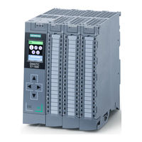
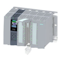
Simatic S7-1500 CPU 1512C-1 PN
Siemens Simatic S7-1500 CPU 1512C-1 PN Manuals
Manuals and User Guides for Siemens Simatic S7-1500 CPU 1512C-1 PN. We have
2
Siemens Simatic S7-1500 CPU 1512C-1 PN manuals available for free PDF download: User Manual, Equipment Manual
Siemens Simatic S7-1500 CPU 1512C-1 PN User Manual (206 pages)
Brand:
Siemens
| Category:
Control Unit
| Size: 6.63 MB
Table of Contents
Preface
4
Table of Contents
6
1 Documentation Guide
9
2 Product Overview
13
Applications of the S7-1500 Cpus
13
Hardware Properties and Firmware Functions
20
Hardware Properties of the CPU Part
21
Firmware Functions of the CPU Part
23
Hardware Properties of the Analog On-Board I/O Module
27
Firmware Functions of the Analog On-Board I/O Module
30
Hardware Properties of the Digital On-Board I/O Module
31
Firmware Functions of the Digital On-Board I/O Module
34
Operator Controls and Display Elements
36
Front View with Closed Front Panel
36
Front View of the CPU Without Front Panel and View from below
38
Rear View
40
Operating Mode Buttons
41
3 Technology Functions
42
High-Speed Counters
42
Functions
43
Counting
43
Measuring
44
Position Detection for Motion Control
45
Additional Functions
46
Configuring the High-Speed Counters
47
General
47
Assignment of the Control Interface of the High-Speed Counters
47
Assignment of the Feedback Interface of the High-Speed Counters
50
Pulse Generators
51
Operating Modes
51
Operating Mode: Pulse-Width Modulation (PWM)
51
Operating Mode: Frequency Output
58
Operating Mode: PTO
62
Functions
67
Function: High-Speed Output
67
Function: Direct Control of the Pulse Output (DQA)
68
Configuring the PWM and Frequency Output Modes
69
Assignment of the Control Interface
69
Handling the SLOT Parameter (Control Interface)
71
Assignment of the Feedback Interface
75
4 Wiring
77
Supply Voltage
77
PROFINET Interfaces
78
Terminal and Block Diagrams
80
Block Diagram of the CPU Part
80
Terminal and Block Diagram of the Analog On-Board I/O
81
Terminal and Block Diagram of the Digital On-Board I/O
90
Addresses of the High-Speed Counters
104
Addresses of the Pulse Generators in the Pulse Width Modulation (PWM) and Frequency Output Modes
107
Addresses of Pulse Generators in the PTO Mode
108
Interconnection Overview of the Inputs
109
Interconnection Overview of Outputs
111
5 Parameters/Address Space
114
Address Space of the Analog On-Board I/O
114
Address Space of the Digital On-Board I/O
116
Address Space of the Pulse Generators
119
Measurement Types and Measuring Ranges of the Analog On-Board I/O
120
Output Type and Output Ranges of the Analog On-Board I/O
121
Parameters of the Analog On-Board I/O
122
Parameters of the Digital On-Board I/O
125
6 Interrupts/Diagnostics Alarms
127
Status and Error Displays
127
Status and Error Displays of the CPU Part
127
Status and Error Displays of the Analog On-Board I/O
130
Status and Error Displays of the Digital On-Board I/O
132
Interrupts and Diagnostics
134
Interrupts and Diagnostics of the CPU Part
134
Interrupts and Diagnostics of the Analog On-Board I/O
135
Interrupts and Diagnostics of the Digital On-Board I/O
138
7 Technical Specifications
141
Dimension Drawings
164
Parameter Data Records
166
Parameter Assignment and Structure of the Parameter Data Records of the Analog On-Board I/O
166
Structure of a Data Record for Input Channels of the Analog On-Board I/O
166
Structure of a Data Record for Output Channels of the Analog On-Board I/O
172
Parameter Assignment and Structure of the Parameter Data Records of the Digital On-Board I/O
175
Structure of a Data Record for Input Channels of the Digital On-Board I/O
176
Structure of a Data Record for Output Channels of the Digital On-Board I/O
178
Parameter Data Records of the High-Speed Counters
180
Parameter Data Records (PWM)
187
Analog Value Processing
189
Conversion Method
189
Representation of Analog Values
196
Representation of Input Ranges
197
Representation of Analog Values in Voltage Measuring Ranges
198
Representation of Analog Values in Current Measuring Ranges
199
Representation of the Analog Values of Resistance-Type Sensors/Resistance-Type
200
Thermometers
200
Measured Values for Wire Break Diagnostics
202
Representation of Output Ranges
203
Representation of Analog Values in the Voltage Output Ranges
204
Representation of Analog Values in the Current Output Ranges
205
Advertisement
Siemens Simatic S7-1500 CPU 1512C-1 PN Equipment Manual (50 pages)
Brand:
Siemens
| Category:
Industrial Equipment
| Size: 4.35 MB
Table of Contents
Table of Contents
4
Introduction
5
Guide Documentation S7-1500/ET 200MP
6
Information Classes S7-1500/ET 200MP
6
SIMATIC Technical Documentation
7
Safety Instructions
10
Security Information
10
Product Overview
11
New Functions
11
Application
12
Hardware Properties
19
Firmware Functions
21
Operating and Display Elements
25
Front View of the CPU with Closed Front Panel
25
Front View of the CPU Without Front Panel and View from below
27
Rear View of the CPU
28
Operating Mode Buttons
29
Connecting up
30
Interrupts, Error Messages, Diagnostics and System Alarms
34
Status and Error Display of the CPU
34
Technical Specifications
38
Dimensional Drawing
50
Advertisement
Related Products
Siemens SIMATIC S7-1500R/H
Siemens S7-1500 PROFIBUS
Siemens SIMATIC S7-300 CPU Data: CPU 315-T-2 DP
Siemens SIMATIC S7-300 FM 350-1
Siemens SIMATIC S7 300 PLC
Siemens SIMATIC S7 3964
Siemens SIMATIC S7 3964R
Siemens SIMATIC S7-300F
Siemens SIMATIC S7-400F
Siemens SINUMERIK 840DE Export version 7.4
Siemens Categories
Industrial Equipment
Controller
Control Unit
Oven
Washer
More Siemens Manuals
Login
Sign In
OR
Sign in with Facebook
Sign in with Google
Upload manual
Upload from disk
Upload from URL