Sign In
Upload
Manuals
Brands
Siemens Manuals
Computer Hardware
Simatic S7-300 CP 341
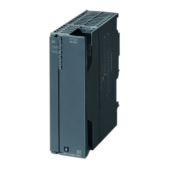
Siemens Simatic S7-300 CP 341 Manuals
Manuals and User Guides for Siemens Simatic S7-300 CP 341. We have
1
Siemens Simatic S7-300 CP 341 manual available for free PDF download: User Manual
Siemens Simatic S7-300 CP 341 User Manual (253 pages)
Point-to-Point Communication, Installation and Parameter Assignment
Brand:
Siemens
| Category:
Computer Hardware
| Size: 4.14 MB
Table of Contents
Preface
3
Commissioning the CP 341
3
Changes Since Edition
4
Table of Contents
9
CP 341 Point-To-Point Communication, Installation and Parameter Assignment Manual, 09/2008, A5E02191071-01
15
Product Description
17
Possible Applications for the CP 341
17
Table 1- 1 CP 341 Module Variants
17
Table 1- 2 Functions of CP 341 Module Variants
18
Design of the CP 341
20
Figure 1-1 Positions of the Module Elements on the CP 341 Communication Processor
20
Figure 1-2 Bus Connector
21
Components for a Point-To-Point Connection with the CP 341
22
Required Hardware Components
22
Table 1- 3 Hardware Components for a Point-To-Point Connection
22
Required Software Components
23
Table 1- 4 Software Components for a Point-To-Point Connection with the CP 341
23
Properties of the Serial Interface
24
RS 232C Interface of the CP 341-RS 232C
24
20Ma-TTY Interface of the CP 341-20Ma TTY
25
Table 1- 5 RS 232C Interface Signals
25
X27 (RS 422/485) Interface of the CP 341-RS 422/485
26
Cables for Connecting the Communication Processor to a Communication Partner
27
Basic Principles of Serial Data Transmission
29
Serial Transmission of a Character
29
Figure 2-1 10-Bit Character Frame
31
Figure 2-2 Character Delay Time
32
Transmission Procedure with a Point-To-Point Connection
33
Transmission Integrity
35
Figure 2-3 Position of the Supplied Protocols of the CP 341 in the Reference Model
35
Data Transmission with the 3964(R) Procedure
38
Principle of the Data Transmission with the 3964(R) Procedure
38
Control Characters of the 3964(R) Procedure
38
Block Checksum
39
Figure 2-4 Block Checksum
39
Sending Data with 3964(R)
40
Figure 2-5 Data Traffic When Sending with the 3964(R) Procedure
40
Receiving Data with 3964(R)
42
Figure 2-6 Data Traffic When Receiving with the 3964(R) Procedure
42
Handling Erroneous Data
44
Figure 2-7 Data Traffic When Erroneous Data Is Received
44
Figure 2-8 Data Traffic in the Event of an Initialization Conflict
45
Figure 2-9 Flow Diagram of the Start-Up of the 3964(R) Procedure
46
Figure 2-10 Flow Diagram of Sending with the 3964(R) Procedure
47
Figure 2-11 Flow Diagram for Receiving with the 3964(R) Procedure (Part 1)
48
Figure 2-12 Flow Diagram for Receiving with the 3964(R) Procedure (Part 2)
49
Data Transmission with the RK 512 Computer Connection
50
Table 2- 1 Structure of Command Message Frame Header (RK 512)
51
Table 2- 2 Monitoring Time Dependent on Transmission Rate for Response Message Frame
52
Table 2- 3 Structure of Response Message Frame Header (RK 512)
52
Sending Data with RK 512
53
Figure 2-13 Data Traffic When Sending with a Response Message Frame
53
Figure 2-14 Sequence of a Continuation SEND Message Frame with a Continuation Response Message Frame
55
Fetching Data with RK 512
56
Figure 2-15 Data Traffic When Fetching with a Response Message Frame
56
Figure 2-16 Sequence of a Continuation FETCH Message Frame with a Continuation Response Message Frame
58
Quasi-Full-Duplex Operation
59
Figure 2-17 Quasi-Full-Duplex Mode
59
RK 512 CPU Requests
60
Figure 2-18 Flow Diagram of Data Transmission with the RK 512 When CPU Requests Are Made
60
Figure 2-19 Flow Diagram of Data Transmission with the RK 512 When Partner Requests Are Made
61
Data Transmission with the ASCII Driver
62
Principle of the Data Transmission with the ASCII Driver
62
Sending Data with the ASCII Driver
62
Figure 2-20 Flowchart of a Send Operation
63
Receiving Data with the ASCII Driver
64
Figure 2-21 Flow Diagram for Receiving with End Criterion "Expiration of Character Delay Time
65
Figure 2-22 Flow Diagram for Receiving with End Criterion "End-Of-Text Character
67
Figure 2-23 Flow Diagram for Receiving with End Criterion "Fixed Message Frame Length
69
RS 485 Mode
71
Figure 2-24 Timing Diagram of Automatic Control of the RS 232C Accompanying Signals
73
Data Transmission with the Printer Driver
75
Figure 2-25 Flow Chart of Printout
77
Configuration Data
79
Configuration Data of the 3964(R) Procedure
79
Table 2- 4 3964(R) Protocol
80
Table 2- 5 Protocol Parameters (3964(R) Procedure)
81
Table 2- 6 Baud Rate/Character Frame (3964(R) Procedure)
82
Table 2- 7 Receive Buffer on CP (3964(R) Procedure)
83
Table 2- 8 X27 (RS 422) Interface (3964(R) Procedure)
83
Figure 2-26 Wiring of the Receiver at the X27 (RS 422) Interface (3964(R) Procedure)
84
Configuration Data of the RK 512 Computer Connection
85
Table 2- 9 RK512 Computer Connection
85
Table 2- 10 Receive Buffer on CP (3964(R) Procedure)
86
Configuration Data of the ASCII Driver
87
Table 2- 11 Protocol Parameters (ASCII Driver)
88
Table 2- 12 Baud Rate/Character Frame (ASCII Driver)
89
Table 2- 13 Data Flow Control (ASCII Driver)
90
Table 2- 14 Receive Buffer on CP (ASCII Driver)
91
Table 2- 15 X27 (RS 422/485) Interface (ASCII Driver)
92
Figure 2-27 Wiring of the Receiver at the X27 (RS 422/485) Interface (ASCII Driver)
93
Parameter Assignment Data of the Printer Driver
94
Table 2- 16 Baud Rate/Character Frame (Printer Driver)
94
Table 2- 17 Data Flow Control (Printer Driver)
95
Table 2- 18 X27 (RS 422/485) Interface (ASCII Driver)
95
Table 2- 19 Page Layout (Printer Driver)
96
Table 2- 20 Character Set (Printer Driver)
97
Table 2- 21 Control Characters (Printer Driver)
97
Table 2- 22 Message Texts (Printer Driver)
98
Conversion and Control Statements for Printout
99
Figure 2-28 Schematic Structure of the Format String
99
Figure 2-29 Schematic Structure of a Conversion Statement
100
Table 2- 23 Display Types in the Conversion Statement
101
Figure 2-30 Schematic Structure of Control Statements
106
Commissioning the CP 341
109
Mounting the CP 341
111
CP 341 Slots
111
Mounting and Dismounting the CP 341
112
Installation Steps
112
Removal Steps
113
Installation Guidelines
113
Figure 4-1 Connection Terminal
113
Configuring and Parameter Assignment the CP 341
115
Parameter Assignment Options
115
Table 5- 1 Configuration Options for the CP 341
115
Installing the Programming Interface
116
Configuring the CP 341
117
Assigning Parameters to the Communications Protocols
118
Identification Data
119
Table 5- 2 Data Record Structure
119
Table 5- 3 Identification Data
119
Table 5- 4 Identification Data of the CP 341 Module
120
Managing the Parameter Data
121
Subsequent Loading of Drivers (Transmission Protocols)
122
Firmware Updates
123
Subsequent Loading of Firmware Updates
123
Table 5- 5 LED Indicators for Firmware Update
125
Viewing the Firmware Version
126
Communication Via Function Blocks
127
Overview of the Function Blocks
128
Table 6- 1 Function Blocks / Functions of the CP 341
128
Using Function Blocks
130
Using the Function Blocks with the 3964(R) Procedure
131
S7 Sends Data to a Communication Partner
132
Table 6- 2 FB P_SND_RK Parameters
134
Figure 6-1 Time Sequence Chart of FB 8 P_SND_RK
135
S7 Receives Data from a Communication Partner
136
Table 6- 3 FB P_RCV_RK Parameters
138
Using the Function Blocks with the RK 512 Computer Connection
140
Sending Data with FB P_SND_RK (Active Request)
142
Table 6- 4 FB 8 P_SND_RK Parameters for "Send Data" Request
144
Table 6- 5 Information in the RK 512 Message Frame Header for "Send Data" Request
145
Receiving Data with FB P_RCV_RK (Passive Request)
147
Table 6- 6 FB 7 P_RCV_RK Parameters for "Receive Data" Request
149
Readying Data with FB P_RCV_RK (Passive Request)
151
Table 6- 7 FB 7 P_RCV_RK Parameters for "Provide Data" Request
153
Fetching Data with P_SND_RK FB (Active Request)
155
Table 6- 8 FB 8 P_SND_RK Parameters for "Fetch Data" Request
157
Table 6- 9 Transmittable Data Types for "Fetch Data" Request
158
Using the System Function Blocks with the ASCII Driver
160
Function Blocks with ASCII Driver
160
Interface Status of the CP 341, Checking
161
Table 6- 11 FC 5 V24_STAT Parameters
162
Interface Outputs of the CP 341, Setting/Resetting
163
Table 6- 12 FC 6 V24_SET Parameters
164
Use of Function Blocks to Output Message Texts to a Printer
165
Table 6- 13 FB 13 P_PRINT_RK Parameters
168
Parameter Assignment of the Function Blocks
170
General Information on Data Block Assignment
170
Supplying the Block Parameters
172
General Information on Program Processing
177
Technical Specifications of the Function Blocks
178
Start-Up Characteristics and Operating Mode Transitions of the CP 341
181
Operating Modes of the CP 341
181
Startup Characteristics of the CP 341
182
Behavior of the CP 341 on Operating Mode Transitions of the CPU
184
Diagnostics with the CP 341
185
Diagnostics Functions of the CP 341
185
Diagnostics Via the Display Elements of the CP 341
186
Diagnostics Messages of the Function Blocks
187
Table 8- 1 Event Classes and Event Numbers
188
Table 8- 2 Event Class 30
199
Error Numbers in the Response Message Frame
200
Diagnostics Via the Diagnostic Buffer of the CP 341
201
Diagnostic Interrupt
203
Programming Example for Standard Function Blocks
205
General Information
205
Device Configuration
206
Settings
207
Blocks Used
208
Installation, Error Messages
209
Activation, Start-Up Program and Cyclic Program
210
Technical Specifications
213
Table A- 10 Transmission Times for the ASCII Driver
218
Table A- 12 Transmission Times with the RK 512 Computer Link
219
B Connecting Cables
221
RS 232C Interface of the CP 341-RS 232C
221
Table B- 2 Pin Assignment for the 9-Pin Sub D Female Connector of the Integrated Interface of the CP 341-20Ma-TTY
228
X27 (RS 422/485) Interface of the CP 341-RS 422/485
235
C Accessories and Order Numbers
239
D Literature on SIMATIC S7
241
Literature on SIMATIC S7
241
Glossary
243
Index
249
Advertisement
Advertisement
Related Products
Siemens Simatic S7-300 31xC Series
Siemens Simatic S7-400
Siemens SIMATIC S7-1200 CP 1243-8 IRC
Siemens SIMATIC S7 400
Siemens SIMATIC S7-400 CP 440
Siemens Simatic S7-300 314C-2 PN/DP
Siemens SENTRON PROFIBUS DPV1 Series
Siemens SMP16-CPU065
Siemens SMP16-CPU06 Series
Siemens SIMATIC NET CP 443-5 Extended
Siemens Categories
Industrial Equipment
Controller
Control Unit
Oven
Washer
More Siemens Manuals
Login
Sign In
OR
Sign in with Facebook
Sign in with Google
Upload manual
Upload from disk
Upload from URL