Sign In
Upload
Manuals
Brands
Siemens Manuals
Control Unit
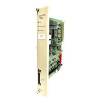
SIMATIC TI535
Siemens SIMATIC TI535 Control Unit Manuals
Manuals and User Guides for Siemens SIMATIC TI535 Control Unit. We have
1
Siemens SIMATIC TI535 Control Unit manual available for free PDF download: Hardware And Installation Manual
Siemens SIMATIC TI535 Hardware And Installation Manual (116 pages)
Brand:
Siemens
| Category:
Control Unit
| Size: 3.62 MB
Table of Contents
Table of Contents
7
Preface
12
Chapter 1 Series 505 System Overview
14
TI525 and TI535 Controllers
15
Functional Relationship of Series 505 Components
17
Introduction
14
Features of the TI525 and TI535
19
Model Differences
19
TI525/TI535 Instruction Set
20
Program Software
21
Program Storage in EEPROM
21
Communication Ports
22
Battery Backup
22
Ladder Memory Protection
23
Chapter 2 Pre-Installation Planning
24
Introduction
24
Operator Safety Switch
27
Safety Considerations
27
Emergency Stop Switch
28
Enclosure Selection
29
JOG or INCH Switch
29
Grounding and Wiring the Equipment
30
Temperature Considerations
30
Chapter 3 Installation
31
Installing the Base Assemblies
31
Series 505 Bases
31
Mounting Dimensions for the Series 505 Bases
32
Installing Base Hardware
33
Rack or Panel Mounting
33
Handling Series 505 Modules
34
Setting TI525 Dipswitches
35
Setting Port Baud Rate - TI525 Models
36
Selecting Battery Backup - TI525 Models
37
Switch Settings - TI525 Battery Backup
37
Selecting Ladder Memory Protection - TI525 Models
38
Switch Settings - TI525 L-Memory Protection
38
Downloading Preset Constants - TI525 Models
39
Switch Settings - TI525 Download/Retain Presets
39
Setting TI535 Dipswitches
40
Selecting I/O Type - TI535 Models
41
Downloading Preset Constants - TI535 Models
42
Switch Settings - TI535 Download/Retain Presets
42
Setting Highest I/O Base Number - TI535 Models
43
Switch Settings - TI535 Highest-Numbered Logical Base
43
Selecting Battery Backup - TI535 Models
44
Switch Settings - TI535 Battery Backup
44
Setting Communication Port Baud Rate -TI535 Models
45
Selecting Ladder Memory Protection - TI535 Models
46
Switch Settings - TI535 L-Memory Protection
46
Installing the Battery
47
Model TI525 Battery Installation
47
Model TI535 Battery Installation
48
Battery Location for TI535 Models
48
Installing System Components
49
Definition of the Series 505 Logical Base
49
System with Local I/O Only
50
Systems with Local and Distributed I/O
51
Numbering Series 505 I/O Points
52
Guidelines for Installing Series 505 Modules
53
Installing the Power Supply
55
Power Supply Jumper
55
Location of Power Supply in Base
56
Installing the PLC
57
Location of PLC in Base
57
Installing the I/O Modules
59
Location of I/O Modules in Base
59
I/O Module Point Assignments
61
Installing the Base Controllers
62
Chapter 4 EPROM/EEPROM Operation
63
Introduction
63
Changes in Mode and Memory after Power up
65
Installing an EPROM/EEPROM in TI525 Models
66
TI525 EPROM/EEPROM Socket and Jumper Pins
67
Installing an EPROM/EEPROM in TI535 Models
68
TI535 EPROM/EEPROM Socket and Jumper Pins
69
Programming the EEPROM
70
Reporting EEPROM Status
72
Status Word Six (STW06)
72
Format of Status Word Six (STW06)
72
Status Words Seven to Nine (STW07-STW09)
73
Editing/Saving Programs Using an EPROM/EEPROM
74
Chapter 5 Startup / Troubleshooting
76
Start-Up Procedures
76
Using the Troubleshooting Tools
79
Reading the LED Indicators
79
LED Indicators
79
AUX Function 29 (Show PLC Diagnostic Cell)
80
Example of AUX Function 29 Screen
80
AUX Function 25 (Display Failed I/O)
81
AUX Function 20 (Run PLC Diagnostics)
81
AUX Function 11 (Partial Restart)
81
AUX Function 12 (Complete Restart)
81
AUX Function 10 (Power-Up Restart)
82
Effects of Aux Functions on Memory Locations
82
Troubleshooting with Status Words
83
Status Word One (STW01)
83
Format of Status Word One (STW01)
83
Status Word Two (STW02)
84
Format of Status Word Two (STW02)
84
Status Word Six (STW06)
85
Format of Status Word Six (STW06)
85
Status Words Seven to Nine (STW07-STW09)
86
Status Word Ten (STW10)
86
Format of Status Word Ten (STW10)
86
Status Words Eleven to Eighteen (STW11-STW18)
87
Format of Status Words Eleven to Eighteen (STW11-18)
87
Example of a Status Word with a Bit Set
88
Clearing PLC Fatal Errors
89
Troubleshooting the EPROM/EEPROM
92
Troubleshooting the Power Supply
93
Spare Parts
94
Appendix A Specifications
95
Grounding
97
Single Point Grounding
97
Guidelines for Ground Connections
98
Sample Ground Connections
99
Appendix B Grounding and Electrical Guidelines
97
Introduction
97
Wiring Guidelines
100
Minimizing Electrical Noise
101
Definition and Source
101
Correcting Noise Problems
102
Noise Suppression
102
Examples of Noise Snubbing
102
Isolation
103
Series 505 Component Power Requirements
104
Series 500 Component Power Requirements
107
Advertisement
Advertisement
Related Products
Siemens SIMATIC TIM 3V-IE DNP3
Siemens SIMATIC TIM 4R-IE DNP3
Siemens Simatic TI405
Siemens TIM 3V-IE DNP3
Siemens TIM 4R-IE DNP3
Siemens SIMATIC TI525
Siemens SIMATIC TI505 386/ATM
Siemens TX-I/O TXM1.8U-ML
Siemens TX-I/O TXM1.6R
Siemens TM FAST
Siemens Categories
Industrial Equipment
Controller
Control Unit
Oven
Washer
More Siemens Manuals
Login
Sign In
OR
Sign in with Facebook
Sign in with Google
Upload manual
Upload from disk
Upload from URL