Sign In
Upload
Manuals
Brands
Siemens Manuals
Control Unit
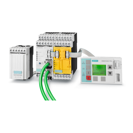
SIMOCODE pro C
Siemens SIMOCODE pro C Manuals
Manuals and User Guides for Siemens SIMOCODE pro C. We have
1
Siemens SIMOCODE pro C manual available for free PDF download: System Manual
Siemens SIMOCODE pro C System Manual (408 pages)
Industrial Controls. Motor management and control devices
Brand:
Siemens
| Category:
Control Unit
| Size: 8.95 MB
Table of Contents
Table of Contents
3
Introduction
9
Important Notes
9
Siemens Industry Online Support
12
Siemens Industry Online Support App
14
Support Request
15
Security Information
16
Current Information about Operational Safety
17
Information about Third-Party Software
18
Recycling and Disposal
22
What Is SIMOCODE Pro
23
Device Series
24
Check List for Selecting a Device Series
24
Modules, Interfaces, Configuration Options
26
Advantages/Benefits/Configuration with SIMOCODE Pro
29
Advantages/Benefits
29
Independent Operation
32
Simplifying Configuration with SIMOCODE Pro
33
Typical Configuration
35
Areas of Application
39
Features
41
Overview of Functions
47
Protection Functions
47
Monitoring Functions
49
Safety-Oriented Tripping
52
Control Functions
53
Communication
54
Standard Functions
57
Freely-Programmable Logic Modules
58
Operating, Service and Diagnostics Data
59
Check List for Selecting a Device Series
61
An Overview of System Components
65
Description of System Components
81
Basic Units (BU)
81
Operator Panel (OP)
85
Operator Panel with Display
88
Description of the Operator Panel with Display
88
Operator Controls and Display Elements of the Operator Panel with Display
92
Menu of the Operator Panel with Display
94
Timing Charts
94
Displays of the Operator Panel with Display
109
Read and Adapt Main Display
112
Display of Measured Values in the Measured Values Display
115
Motor Protection and Motor Control Status
117
Display of Statistical and Maintenance-Relevant Information on the Statistics/Maintenance Display
119
Status Display for Fieldbus Communication
120
Displays the Current Status of All Device I/Os
122
Parameters
124
Adapt Display Settings
126
Resetting, Testing and Parameterizing Via Commands
129
Displaying All Pending Messages
130
Displaying All Pending Warnings
130
Displaying All Pending Faults
130
Reading the Device's Internal Error Buffer
130
Reading the Device's Internal Event Memory
131
Identification of the Motor Feeder and the SIMOCODE Pro Components
132
Current Measuring Modules (IM) for the SIMOCODE Pro C, SIMOCODE Pro S, and SIMOCODE Pro V Device Series
133
Current / Voltage Measuring Modules (UM, UM+) for the SIMOCODE Pro V High Performance Device Series
135
Decoupling Module (DCM) for 1St Generation Current/Voltage Measuring Modules (E.g. 3UF711.1AA000)
142
Spectrum of the Expansion Modules
146
Digital Module (DM)
147
Fail-Safe Digital Module (DM-F)
148
Analog Module (AM)
151
Ground-Fault Module (EM)
152
Temperature Module (TM)
153
Multifunction Module
154
Configuration Information for SIMOCODE Pro V When Using an Older Basic Unit
155
Configuration Notes for Use of a SIMOCODE Pro V MR and SIMOCODE Pro V EIP Basic Unit
158
Compartment Identification
159
Applications and Advantages of Compartment Identification
159
Hardware and Software Requirements for Compartment Identification
162
Operating Compartment Identification
163
Mounting, Wiring, Interfaces, Compartment Identification
167
Commissioning and Service Compartment Identification
170
Alarm, Fault, and System Events for Compartment Identification
171
Compartment Identification Dimension Drawings
172
Technical Data Compartment Identification
173
Accessories
175
3UF50 Compatibility Mode
179
Application, Win-SIMOCODE-DP Converter
179
Diagram of Send and Receive Data
180
Diagram of Diagnostics Data
181
Mounting, Wiring, Connecting, System Interfaces, Configuration Guidelines
185
Mounting
185
Mounting Basic Units, Expansion Modules, and the Decoupling Module
185
Mounting the Bus Terminal
188
Mounting of Digital Modules DM-F Local and DM-F Profisafe
189
Mounting of Current Measuring Modules
189
Mounting the Current / Voltage Measuring Modules
191
Mounting of the Operator Panel and Operator Panel with Display
193
Wiring, Connecting
195
Wiring Basic Units, Expansion Modules and the Decoupling Module
195
Wiring Digital Modules DM-F Local and DM-F Profisafe
221
Wiring of Current Measuring Modules
226
Wiring of Current / Voltage Measuring Modules
228
Measuring Current with an External Current Transformer (Interposing Transformer)
233
System Interfaces
236
Information about the System Interfaces
236
System Interfaces on Basic Units, Expansion Modules, Decoupling Module, Current Measuring Modules and Current / Voltage Measuring Modules
237
System Interfaces on the Digital Modules DM-F Local and DM-F Profisafe
242
System Interfaces on the Operator Panel and the Operator Panel with Display
243
Closing the System Interfaces with the System Interface Cover
247
PROFIBUS DP to a 9-Pole SUB-D Socket
248
Ethernet Cable to RJ45 Socket (PROFINET and Ethernet/Ip)
249
Modbus RTU Connection to the SIMOCODE Pro Device
250
Configuration Guidelines
252
Configuration Guidelines on PROFIBUS DP
252
Configuration Guidelines on PROFINET
254
Commissioning, Service, Troubleshooting
255
General Information about Commissioning and Service
255
Commissioning
257
Commissioning with PROFIBUS
257
PROFIBUS Commissioning Steps
257
Setting the PROFIBUS DP Address
258
Diagnostics Via LED Display on the Basic Unit and on the Operator Panel (PROFIBUS)
259
Diagnostics Via LED Display on the Modules DM-F Local or DM-F Profisafe
259
Commissioning with PROFINET
260
PROFINET Commissioning Steps
260
Setting IP Parameters and PROFINET Device Name
261
Setting the Time Manually after Switch-On or Recovery of the Supply Voltage
263
Diagnostics Via LED Display on the Basic Unit and on the Operator Panel (PROFINET)
264
Commissioning with Modbus
265
Commissioning with Modbus RTU
265
Commissioning with Ethernet/Ip
270
Ethernet/Ip Commissioning Steps
270
Setting IP Parameters and EIP Device Name
271
Set the Time Manually after Switch-On or Recovery of the Supply Voltage
273
Diagnostics Via LED Display on the Basic Unit and on the Operator Panel with Ethernet/Ip
274
Service
275
Preventive Maintenance
275
Backing up and Saving Parameters
277
Replacing SIMOCODE Pro Components
279
Exchanging a 3UF52 Operator Panel for a 3UF720 Operator Panel
283
Restoring Factory Settings
285
Firmware Update of Device Components
286
Support Request
287
Troubleshooting
288
Error Buffer
288
Event Memory
290
Alarms, Faults, and System Events - Error Handling
291
Safety and Commissioning Information for Ex Areas
303
Motor Protection Functions (Overload Protection, Thermistor Protection)
303
Module Integration
303
Information and Standards
304
Installation and Commissioning - Motor Protection Functions (Overload Protection, Thermistor Protection)
305
Operating Instructions
305
Setting the Rated Motor Current
305
SIMOCODE Pro with Thermistor Input
307
Sensor Circuit Wiring
308
Short-Circuit Protection for Type of Coordination 2 According to IEC 60947-4-1
309
Cable Protection
309
Test
309
Further Safety Guidelines
311
Ambient Conditions
311
Safety Values
312
Maintenance and Repairs
312
Warranty
312
Further Information
313
Dry-Running Protection for Centrifugal Pumps by Active Power Monitoring
314
Module Integration
314
Information and Standards
314
Installation and Commissioning - Dry-Running Protection for Centrifugal Pumps by Means of Active Power Monitoring
318
Operating Instructions
318
General Information on Installation and Commissioning
318
Special Conditions for Commissioning and Operation
319
Setting the Parameters
320
Line Protection
322
Test
322
Further Safety Information
325
Environmental Conditions
325
Safety Values
326
Periodic Tests
326
Maintenance and Repair
326
Warranty
327
More Information
327
Technical Data
329
Common Technical Data
329
Technical Specifications of the SIMOCODE Pro C / Pro S / Pro V PB / Pro V MR Basic Units
332
Technical Specifications of the SIMOCODE Pro V PN / Pro V PN GP / Pro V EIP Basic Units
337
Technical Data of the Current Measuring Modules and the Current / Voltage Measuring Modules
340
Technical Data of the Decoupling Module
345
Technical Data of the Expansion Modules
346
Technical Data of the Digital Modules
346
Technical Data, Digital Modules DM-F Local and DM-F Profisafe
347
Technical Data of the DM-F Local Digital Module
349
Technical Data of the DM-F-Profisafe Digital Module
351
Safety-Related Technical Data of the Digital Modules DM-F Local and DM-Fprofisafe
352
Technical Data of the Analog Module
352
Technical Data of the Ground-Fault Module 3UF7500-1AA00-0
354
Technical Data of the Ground-Fault Module 3UF7510-1AA00-0
355
Technical Data of the Temperature Module
356
Technical Data of the Multifunction Module
357
Technical Data of the Operator Panels
360
Technical Data of the Operator Panel
360
Technical Data of the Operator Panel with Display
361
Technical Data of the Compartment Identification
363
Short-Circuit Protection with Fuses for Motor Feeders for Short-Circuit Currents up to 100 Ka and 690 V for 1St Generation Current / Voltage Measuring Module
364
Typical Reaction Times
365
Typical Reaction Times of the SIMOCODE Pro C/V Device Series
365
Typical Response Times of SIMOCODE Pro S Device Series
366
Typical Reaction Times of the Modbus RTU Device Series
367
Technical Data in Siemens Industry Online Support
368
Cax Data, Dimension Drawings
369
Cax Data
369
A.1 List of Abbreviations
371
Glossary
375
Index
399
List of Abbreviations
371
Advertisement
Advertisement
Related Products
Siemens SIMOCODE pro
Siemens SIMOCODE pro PCS 7
Siemens SIMOCODE pro S
Siemens SIMOCODE pro V PB
Siemens SIMOCODE pro V MR
Siemens SIMOCODE pro V EIP
Siemens SIMOCODE DP
Siemens SIMOCODE DP PCS 7
Siemens SIMOCODE pro DM-F Local
Siemens SIMOTICS CONNECT 400
Siemens Categories
Industrial Equipment
Controller
Control Unit
Oven
Washer
More Siemens Manuals
Login
Sign In
OR
Sign in with Facebook
Sign in with Google
Upload manual
Upload from disk
Upload from URL