Sign In
Upload
Manuals
Brands
Siemens Manuals
Control Unit
SINAMICS G120 CU240B-2
Siemens SINAMICS G120 CU240B-2 Manuals
Manuals and User Guides for Siemens SINAMICS G120 CU240B-2. We have
2
Siemens SINAMICS G120 CU240B-2 manuals available for free PDF download: Operating Instructions Manual
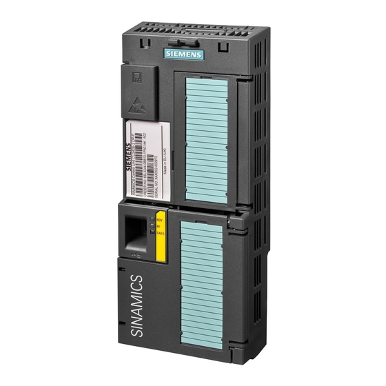
Siemens SINAMICS G120 CU240B-2 Operating Instructions Manual (290 pages)
With the Control Units
Brand:
Siemens
| Category:
DC Drives
| Size: 12.17 MB
Table of Contents
Table of Contents
5
1 Introduction
11
About this Manual
11
Guide through this Manual
12
Overview of Documentation
13
Adapting the Inverter in Line with the Application
15
General Basics
15
Parameter
16
Parameters with Follow-On Parameterization
16
Parameter Changes, Which Subsequently Result in Internal Calculations
17
Frequently Required Parameters
18
Extended Scope for Adaptation
20
BICO Technology: Basic Principles
20
BICO Technology: Example
22
2 Description
25
Modularity of the Converter System
25
Overview of Control Units
26
Power Module
27
Reactors and Filters
29
3 Connecting
31
Procedure for Installing the Frequency Inverter
31
Installing Reactors and Filters
32
Installing the Power Module
33
Installing Power Modules
33
Dimensions, Hole Drilling Templates, Minimum Clearances, Tightening Torques
34
Connection Overview for Power Module
43
Connecting the Line Supply and Motor
44
EMC-Compliant Connection
46
Installing Control Unit
50
Snapping the Control Unit Onto the Power Module
50
Interfaces, Connectors, Switches, Terminal Blocks and Leds of the CU
51
Terminal Strips on CU240B-2 and CU240E-2 Control Units
52
Wiring Terminal Strips
54
4 Commissioning
55
Typical Commissioning Scenarios
55
Preparing Commissioning
57
Commissioning with Factory Settings
60
Prerequisites for Using the Factory Settings
60
Inverter Factory Setting
60
Pre-Assignment of the Inputs and Outputs
62
Wiring Examples for the Factory Settings
64
Commissioning with the BOP-2
68
Inserting the BOP-2
68
Display of the BOP-2
68
Menu Structure
69
Changing Parameter Values
70
Basic Commissioning
71
Additional Settings
72
Commissioning with STARTER
73
Overview
73
Requirements
73
Installing USB Drivers
74
System Settings in the PC/PG for the USB Interface
75
Creating a STARTER Project
77
Establishing an Online Connection between the PC and Converter (Going "Online")
80
Basic Commissioning
81
Additional Settings
84
Back-Up the Settings and Transfer
86
External Data Backup and Series Commissioning
86
Backing up and Transferring Settings Using STARTER
86
Backing up and Transferring Settings Using BOP-2
87
Saving Setting on Memory Card
87
Transferring the Setting from the Memory Card
89
Safely Remove the Memory Card
90
Other Ways to Back up Settings
91
Restoring the Factory Setting
92
5 Configuring the Terminal Block
93
Digital Inputs
93
Fail-Safe Digital Input
95
Digital Outputs
96
Analog Inputs
97
Analog Outputs
100
6 Connection to a Fieldbus
103
Data Exchange Via the Fieldbus
103
Setting the Bus Address Via DIP Switch
104
Communication Via PROFIBUS
105
Configuring Communication Via PROFIBUS
105
Task
105
Required Components
106
Setting the PROFIBUS Address
107
Creating a STEP 7 Project
107
Inverter GSD
108
Inserting the Inverter into the STEP 7 Project
109
Communication Parameters
111
Cyclic Communication
112
Control and Status Words
113
Data Structure of the Parameter Channel
118
Acyclic Communication
123
Acyclic Communication over PROFIBUS DP (DP V1)
123
STEP 7 Program Examples
124
STEP 7 Program Example for Cyclic Communication
124
STEP 7 Program Example for Acyclic Communication
126
Communication Via RS485
130
Integrating Inverters into a Bus System Via the RS485 Interface
130
Communication Via USS
131
General Information about Communication with USS Via RS485
131
Structure of a USS Telegram
133
User Data Range of the USS Telegram
135
Data Structure of the USS Parameter Channel
135
USS Read Request
140
USS Write Job
140
USS Process Data Channel (PZD)
141
Telegram Monitoring
142
Communication over Modbus RTU
144
Parameters for Modbus Communication Settings
144
Modbus RTU Telegram
146
Baud Rates and Mapping Tables
147
Write and Read Access Via FC 3 and FC 6
150
Communication Procedure
152
7 Functions
155
Overview of the Inverter Functions
155
Inverter Control
157
Command Sources
158
Setpoint Sources
159
Selecting the Setpoint Source
159
Analog Input as Setpoint Source
160
Motorized Potentiometer as Setpoint Source
160
Fixed Speed as Setpoint Source
163
Running the Motor in Jog Mode (JOG Function)
165
Specifying the Motor Speed Via the Fieldbus
166
Setpoint Calculation
166
Minimum Speed and Maximum Speed
166
Ramp-Function Generator
167
Motor Control
168
V/F Control
169
V/F Control with Linear Characteristic
170
Additional Characteristics for the V/F Control
171
Optimizing with a High Break Loose Torque and Brief Overload
172
Vector Control
173
Properties of Vector Control
173
Commissioning Vector Control
173
Torque Control
174
Protection Functions
175
Inverter Temperature Monitoring
175
Motor Temperature Monitoring Using a Temperature Sensor
176
Protecting the Motor by Calculating the Motor Temperature
178
Overcurrent Protection
178
Limiting the Maximum DC Link Voltage
179
Load Torque Monitoring (System Protection)
181
Speed and Load Failure Via Digital Input
183
Status Messages
186
Overview, Evaluating the Inverter State
186
System Runtime
186
Technological Functions
187
Braking Functions of the Inverter
187
Comparison of Electrical Braking Methods
187
DC Braking
190
Compound Braking
192
Dynamic Braking
194
Braking with Regenerative Feedback to the Line
196
Motor Holding Brake
197
Automatic Restart and Flying Restart
203
Flying Restart - Switching on While the Motor Is Running
203
Automatic Switch-On
205
PID Technology Controller
209
Logical and Arithmetic Functions Using Function Blocks
210
Safe Torque off (STO) Safety Function
214
Prerequisite for STO Use
214
Permitted Sensors
214
Connecting Fail-Safe Digital Inputs
215
F-DI Signal Filtering
216
Forced Dormant Error Detection
219
Password
220
Commissioning the STO
220
Defining Commissioning Method
221
Assigning Parameters to the STO
221
Activate Settings
222
Multiple Assignment of the DI
222
Acceptance Test - Following Completion of Commissioning
224
Prerequisites and Authorized Persons
224
Complete Acceptance Test
224
Reduced Acceptance Test
225
Documentation
226
Completion of the Certificate
228
Switchover between Different Settings
230
Changing over the Command Data Sets (Manual, Automatic)
230
Switching over Drive Data Sets (Different Motors Connected to an Inverter)
233
8 Service and Maintenance
237
Replacing the Inverter Components
237
Replacing the Control Unit
239
Replacing the Power Module
241
9 Alarms, Faults and System Messages
243
Operating States Indicated on Leds
244
Alarms
246
List of Warnings
249
Faults
251
List of Faults
256
10 Technical Data
261
Technical Data, CU240B-2 Control Unit
261
Technical Data, CU240E-2 Control Unit
262
Technical Data, Power Modules
263
Technical Data, PM240
265
Technical Data, PM240-2
271
Technical Data, PM250
274
Technical Data, PM250-2
277
Technical Data, PM260
281
Index
283
Advertisement
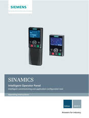
Siemens SINAMICS G120 CU240B-2 Operating Instructions Manual (118 pages)
Intelligent Commissioning and Application Configuration Tool
Brand:
Siemens
| Category:
Control Panel
| Size: 8.7 MB
Table of Contents
Table of Contents
5
1 Safety Notes
9
2 Overview
11
Introduction
11
Layout and Functions
12
Screen Icons
15
Menu Structure
16
3 Installation
17
Fitting the IOP
17
Initial Set-Up
18
User Definable Labels for the Status Screen
22
Firmware and Language Upgrade
23
4 Wizards
25
Example Wizard
31
Basic Commissioning with IOP
33
Wiring Diagrams
36
5 Control
45
Custom Hand Mode
49
Startup in Hand Mode
53
Hand/Auto Disable
54
6 Menu
57
Overview
57
Diagnostics
58
Parameters
62
Up/Download
68
Custom Parameter Sets
69
Extras
73
I/O Editor
85
Write Protection
87
Know-How Protection
89
7 Options
105
Door Mounting Kit
105
Hand-Held Device
107
Advertisement
Related Products
Siemens Sinamics G120 CU240E
Siemens Sinamics G120 CU240S PN-F
Siemens Sinamics G120 CU240S DP
Siemens Sinamics G120 CU240S PN
Siemens SINAMICS G120 CU250S-2 Series
Siemens SINAMICS G120 CU230P-2
Siemens SINAMICS G120 CU240E-2
Siemens SINAMICS G120P CU230P-2
Siemens SINAMICS G120D CU240D-2 DP
Siemens SINAMICS G120D CU250D-2 DP-F
Siemens Categories
Industrial Equipment
Controller
Control Unit
Oven
Washer
More Siemens Manuals
Login
Sign In
OR
Sign in with Facebook
Sign in with Google
Upload manual
Upload from disk
Upload from URL