Sign In
Upload
Manuals
Brands
Siemens Manuals
Media Converter
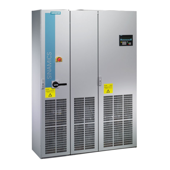
SINAMICS S150 NEMA
Siemens SINAMICS S150 NEMA Manuals
Manuals and User Guides for Siemens SINAMICS S150 NEMA. We have
2
Siemens SINAMICS S150 NEMA manuals available for free PDF download: Operating Instructions Manual
Siemens SINAMICS S150 NEMA Operating Instructions Manual (863 pages)
Converter Cabinet Units
Brand:
Siemens
| Category:
Media Converter
| Size: 25.69 MB
Table of Contents
Legal Information
4
Technical Support
6
Internet Address
7
General Safety Instructions
21
Handling Electrostatic Sensitive Devices (ESD)
27
Industrial Security
28
Residual Risks of Power Drive Systems
30
Device Overview
31
Chapter Content
31
Field of Application
31
Wiring Principle
36
Rating Plate
37
Date of Manufacture
39
Mechanical Installation
43
Transportation and Storage
43
Installation
45
Mechanical Installation: Checklist
46
Requirements for Installation Location
47
Shipping and Handling Monitors
48
Required Tools
50
Removing the Crane Transport Aids
52
Connection to the Foundation
54
Line Connection from above (Option M13), Motor Connection from above (Option M78)
55
Electrical Installation
57
Chapter Content
57
Checklist for Electrical Installation
58
Required Tool
63
Important Safety Precautions
64
Introduction to EMC
65
Noise Emissions
66
EMC-Compliant Design
67
Cable Installation
68
Shield Connection
68
Power Connections
69
Cable Lugs
70
Connection Cross-Sections, Cable Lengths
71
Conductor Cross-Sections
71
Direction of Motor Rotation
75
Connection Overview
88
Connection Example
90
Electrical Installation
92
X122: Digital Inputs/Outputs
92
X132: Digital Inputs/Outputs
94
Bus Terminating Resistor
97
PROFIBUS Address Switches
98
Setting the PROFIBUS Address
98
X127: LAN (Ethernet)
99
DIAG Button
102
Customer Terminal Block
104
Customer Terminal Block (-A60)
106
Terminal Descriptions
110
Additional Connections
116
Electrical Installation
119
Technical Data
119
DV/Dt Filter Plus Voltage Peak Limiter (Option L10)
122
EMERGENCY STOP Category 1; 24 V DC (Option L60)
133
Installing the Braking Resistor
134
Connecting the Braking Resistor
136
Diagnosis and Duty Cycles
139
Threshold Switch
139
Electrical Installation
140
Insulation Monitor (Option L87)
144
Safety Instructions
144
CBC10 CAN Communication Board (Option G20)
148
Interface Overview
149
Communication Board Ethernet CBE20 (Option G33)
151
Mac Address
152
X1400 Ethernet Interface
153
Temperature Sensor Connections
155
Connection Examples
158
Parameter Settings
164
Connection Example
168
SMC30 Sensor Module Cabinet-Mounted (Option K50)
170
Voltage Sensing Module for Determining the Actual Motor Speed and the Phase Angle (Option K51)
179
Additional Customer Terminal Block TM31 (Option G61)
180
Terminal Module for Activation of "Safe Torque Off" and "Safe STOP 1" (Option K82)
182
Safe Brake Adapter SBA 230 V AC (Option K88)
185
Control Unit CU320-2 PN (Option K95)
186
Chapter Content
201
Installing the STARTER Commissioning Tool
204
Procedure for Commissioning with STARTER
205
Creating the Project
205
The STARTER Project Wizard
207
Selecting Options
215
Configuring the Infeed
217
Transferring the Drive Project
241
Commissioning with STARTER Via Ethernet
243
The AOP30 Operator Panel
249
First Commissioning
250
Selecting the Language
251
Basic Commissioning
252
Status after Commissioning
261
Parameter Reset to Factory Settings
263
Operation
265
Chapter Content
265
General Information about Command and Setpoint Sources
266
Function Diagrams
266
Basic Information about the Drive System
267
Parameter Categories
268
Drive Objects
270
CDS: Command Data Set
272
BICO Technology: Interconnecting Signals
277
Interconnecting Signals Using BICO Technology
279
Internal Encoding of the Binector/Connector Output Parameters
280
Propagation of Faults
283
Command Sources
284
"Profidrive" Default Setting
284
"TM31 Terminals" Default Setting
286
Setpoint Sources
288
Analog Inputs
288
Motorized Potentiometer
290
Signal Flow Diagram
291
Function Diagram
291
Fixed Speed Setpoints
291
Control Via the Operator Panel
293
Menu: Operation Screen
295
Parameterization Menu
296
Drive Commissioning
298
Complete Commissioning
298
Motor Identification
298
Device Commissioning
299
Drive Diagnostics
299
AOP Settings
301
Control Settings
301
Display Settings
301
Date Format
307
Keyboard Test
310
Sprachauswahl/Language Selection
311
Operation Via the Operator Panel (LOCAL Mode)
311
LOCAL/REMOTE Key
312
Switching between Clockwise and Counter-Clockwise Rotation
313
Increase Setpoint / Decrease Setpoint
313
AOP Setpoint
314
Operator Input Inhibit / Parameterization Inhibit
316
Faults and Alarms
317
Fault and Alarm Displays
318
Saving the Parameters Permanently
319
Parameterization Errors
319
Communication According to Profidrive
320
General Information
320
Communication Types
321
Application Classes
322
Operation
323
Cyclic Communication
324
Telegrams and Process Data
325
Overview of Control Words and Setpoints
328
Overview of Status Words and Actual Values
328
Acyclic Communication
329
Structure of Requests and Responses
331
Example 2: Writing Parameters (Multi-Parameter Request)
339
Standard Diagnostics
347
Channel-Related Diagnostics
349
Further Information about Profidrive Communication
350
Communication Via PROFIBUS DP
351
PROFIBUS Connection
352
Cable Routing
354
General Information about PROFIBUS DP
355
Master and Slave
356
Control Via PROFIBUS
358
Monitoring: Telegram Failure
360
Communication Via PROFINET IO
364
General Information about PROFINET IO for SINAMICS
368
Real-Time (RT) and Isochronous Real-Time (IRT) Communication
369
Ip Address Assignment
371
Dynamic IP Address Assignment
373
Communication Channels
376
Communication with CBE20
377
PROFINET Media Redundancy
378
Diagnostics Leds
380
Additional Information
381
Faults and Alarms
381
Principle of Operation
384
Activating the Energy Saving Mode
386
Communication Via SINAMICS Link
390
Transmission Time
391
Configuring and Commissioning
394
Sending Data
394
Receiving Data
396
Operation
397
Communication Failure When Booting or in Cyclic Operation
401
Function Diagrams and Parameters
402
Communication Via Ethernet/Ip
403
Configuring Communication
405
Supported Objects
406
Faults and Alarms
418
Modbus Functionality
419
Mapping Tables
422
Operation
423
Write and Read Access Using Function Codes
425
Communication Details
428
Communication Procedure
431
Communication Services and Used Port Numbers
433
Parallel Operation of Communication Interfaces
435
General Information
435
Engineering Software Drive Control Chart (DCC)
439
Setpoint Channel and Closed-Loop Control
441
Setpoint Channel
442
Setpoint Addition
442
Direction Reversal
443
Function Diagram
443
Skip Frequency Bands and Minimum Speed
444
Signal Flow Diagram
444
Speed Limitation
445
Ramp-Function Generator
446
Ramp-Function Generator Tracking
447
Function Diagrams
449
Voltage Boost
453
Resonance Damping
456
Slip Compensation
457
Vector Control Without Encoder
460
Permanent-Magnet Synchronous Motors
463
Function Diagrams
466
Vector Control with Encoder
467
Speed Controller
469
Speed Controller Pre-Control (Integrated Pre-Control with Balancing)
473
Reference Model
476
Speed Controller Adaptation
477
Droop Function
479
Open Actual Speed Value
481
Function Diagrams
482
Closed-Loop Torque Control
483
Torque Limiting
485
Current Setpoint Filters
487
Current Controller Adaptation
488
Supplementary Conditions
490
Short Circuit Protection
492
Output Terminals
493
Analog Outputs
494
List of Signals for the Analog Signals
495
Digital Outputs
498
Delivery Condition
498
Functions, Monitoring and Protective Functions
501
Line and DC Link Identification
502
Harmonics Controller
503
Function Diagram
504
Drive Functions
507
Motor Data Identification
508
Rotating Measurement and Speed Controller Optimization
511
Efficiency Optimization
515
Function Diagrams
517
Fast Magnetization for Induction Motors
518
Alarms and Faults
519
VDC Control
521
Function Diagram
524
Automatic Restart Function
525
Automatic Restart Mode
526
Flying Restart
528
Flying Restart Without Encoder
530
Flying Restart with Encoder
533
Motor Changeover
536
Example of Changing over between Two Motors
536
Function Diagrams
538
Friction Characteristic Curve
539
Function Diagram
540
Armature Short-Circuit Braking, DC Braking
541
External Armature Short-Circuit Braking
541
Internal Armature Short-Circuit Braking
543
Increasing the Output Frequency
546
Default Pulse Frequencies
547
Increasing the Pulse Frequency
547
Maximum Output Frequency Achieved by Increasing the Pulse Frequency
548
Derating Behavior at Increased Pulse Frequency
549
Pulse Frequency Wobbling
550
Runtime (Operating Hours Counter)
552
Simulation Mode
553
Function Diagrams
556
Unit Changeover
556
Unit Groups
557
Simple Brake Control
558
Signal Connections
559
Energy Saving Indicator for Pumps, Fans, and Compressors
562
Deactivating Write Protection
565
Know-How Protection
567
Activating Know-How Protection
569
Deactivating Know-How Protection
571
Changing the Know-How Protection Password
572
OEM Exception List
572
Overview of Important Parameters
576
Essential Service Mode
576
Automatic Restart
579
Function Diagrams
580
Web Server
581
General Information
581
Data Transfer
582
Access Rights
582
Browsers Supported
583
Starting the Web Server
585
Web Server Configuration
587
Display Areas
588
Device Info
588
Overview of Important Parameters
590
Principle of Operation
592
Troubleshooting, Causes and Remedies
600
Position Tracking
605
Function Diagram
610
Extended Functions
610
Technology Controller
610
Function Diagrams
613
Bypass Function
613
Transfer Process
616
Bypass with Synchronizer Without Degree of Overlapping (P1260 = 2)
618
Bypass Without Synchronizer (P1260 = 3)
620
Extended Brake Control
623
Function Diagrams
626
Extended Monitoring Functions
628
Moment of Inertia Estimator
630
Function Diagram
635
Position Control
636
Indexed Actual Value Acquisition
639
Load Gear Position Tracking
639
Commissioning Position Tracking Load Gear Using STARTER
645
Position Controller
647
Monitoring Functions
648
Position Monitoring
648
Following Error Monitoring
649
Measuring Probe Evaluation and Reference Mark Search
650
Basic Positioner
652
Mechanical System
654
Maximum Velocity
656
Function Diagram
661
Set Reference Point
663
Absolute Encoder Adjustment
664
Function Diagrams
673
Traversing Blocks
680
Parameter Sets
680
Function Diagram
685
Fixed Stop Reached
686
Vertical Axes
688
Function Diagrams
688
Status Signals
692
Monitoring Functions and Protective Functions
697
Protecting Power Components
697
Thermal Monitoring and Overload Responses
698
Blocking Protection
701
Stall Protection (Only for Vector Control)
702
Thermal Motor Protection
703
Temperature Sensor Evaluation
706
Thermal Motor Models
707
Temperature Measurement Via TM150 (Option G51)
712
Forming Groups of Temperature Sensors
715
Chapter Content
719
Diagnostics Via Leds
720
Diagnostics Via Parameters
730
Indicating and Rectifying Faults
734
Maintenance and Servicing
739
Chapter Content
739
Maintenance
740
Tightening Torques for Screw Connections
741
Installation Device
742
Article Number
742
Using Crane Lifting Lugs to Transport Power Blocks
743
Replacing Components
745
Replacing the Filter Mats
745
Preparatory Steps
747
Removal Steps
747
Installation Steps
747
Replacing the Fan
764
Replacing the Fan, Size HX
768
Replacing Cylindrical Fuses
787
Replacing the Backup Battery for the Cabinet Operator Panel
792
Forming the DC Link Capacitors
794
Messages after Replacing DRIVE-Cliq Components
795
Automatic Firmware Update
795
Upgrading the Cabinet Unit Firmware
796
Loading the Firmware
797
Technical Specifications
799
General Data
800
Derating Data
801
Overload Capability
805
Environmental Compatibility
829
List of Abbreviations
830
Parameter Macros
839
Advertisement
Siemens SINAMICS S150 NEMA Operating Instructions Manual (822 pages)
Converter cabinet units 15HP-1250HP
Brand:
Siemens
| Category:
Media Converter
| Size: 22.67 MB
Table of Contents
Stw1
320
1 Actual Speed Value Part 1
384
3 Actual Torque Value Part 1
384
Current Fault Code
384
Telegram Word
384
Table of Contents
385
Slots in the Send Buffer P8871[X]
385
Telegram Word
385
Control Word, Faults/Alarms
386
Missing Enables Part 1
386
R2131
386
Advertisement
Related Products
Siemens sinamics dcp
Siemens SINAMICS DC MASTER
Siemens SINAMICS MV
Siemens SINAMICS PCS
Siemens SICLOCK PCON
Siemens SIMOVERT MV Series
Siemens ISOLATED MULTI-DROP SG-6048-01
Siemens SINAMICS S110
Siemens SINAMICS S150
Siemens SINAMICS Series
Siemens Categories
Industrial Equipment
Controller
Control Unit
Oven
Washer
More Siemens Manuals
Login
Sign In
OR
Sign in with Facebook
Sign in with Google
Upload manual
Upload from disk
Upload from URL