Sign In
Upload
Manuals
Brands
Siemens Manuals
Control Systems
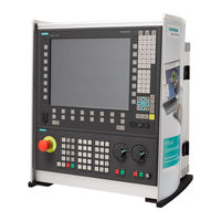
SINUMERIK 840DE
Siemens SINUMERIK 840DE Manuals
Manuals and User Guides for Siemens SINUMERIK 840DE. We have
13
Siemens SINUMERIK 840DE manuals available for free PDF download: Function Manual, Diagnostics Manual, Programming Manual, Operator's Manual, Operation & Programming Manual, User Manual
Siemens SINUMERIK 840DE Function Manual (2184 pages)
Brand:
Siemens
| Category:
Control Systems
| Size: 15.69 MB
Table of Contents
Table of Contents
1792
Keep Tool Radius Compensation Constant
1874
Alarm Behavior
1877
Intersection Procedure for Polynomials
1878
G461/G462 Approach/Retract Strategy Expansion
1879
Toolholder with Orientation Capability
1883
General
1883
Kinematic Interaction and Machine Design
1890
Oblique Machining with 3 + 2 Axes
1898
Machine with Rotary Work Table
1899
Procedure When Using Toolholders with Orientation Capability
1904
Programming
1909
Supplementary Conditions and Control System Response for Orientation
1910
Incrementally Programmed Compensation Values
1913
G91 Extension
1913
Machining in Direction of Tool Orientation
1914
Basic Tool Orientation
1916
Special Handling of Tool Compensations
1920
Relevant Setting Data
1920
Mirror Tool Lengths (SD42900 $SC_MIRROR_TOOL_LENGTH)
1922
Mirror Wear Lengths (SD42920 $SC_WEAR_SIGN_CUTPOS)
1923
Tool Length and Plane Change (SD42940 $SC_TOOL_LENGTH_CONST)
1924
Tool Type (SD42950 $SC_TOOL_LENGTH_TYPE)
1926
Temperature Offsets in Tool Direction (SD42960 $SC_TOOL_TEMP_COMP)
1927
Tool Lengths in the WCS, Allowing for the Orientation
1927
Tool Length Offsets in Tool Direction
1927
Sum Offsets and Setup Offsets
1933
General
1933
Description of Function
1934
Activation
1937
Examples
1944
Upgrades for Tool Length Determination
1945
Taking the Compensation Values into Account Location-Specifically and Workpiece- Specifically
1945
Functionality of the Individual Wear Values
1950
Working with Tool Environments
1954
General
1954
Saving with TOOLENV
1954
Delete Tool Environment
1957
How Many Environments and Which Ones Are Saved
1958
Read T, D, DL from a Tool Environment
1959
Read Tool Lengths, Tool Length Components
1960
Tool Lengths L1, L2, L3 Assignment: LENTOAX
1967
Supplementary Conditions
1971
Flat D Number Structure
1971
SD42935 Expansions
1972
Example: Toolholder with Orientation Capability
1973
Toolholder with Orientation Capability
1973
Examples
1973
Example of Toolholder with Orientation Capability with Rotary Table
1974
Basic Tool Orientation Example
1977
Calculation of Compensation Values on a Location-Specific and Workpiece-Specific Basis
1977
Examples 3-6: SETTCOR Function for Tool Environments
1980
Data Lists
1987
Machine Data
1987
NC-Specific Machine Data
1987
Channelspecific Machine Data
1988
Axis/Spindlespecific Machine Data
1989
Setting Data
1990
Channelspecific Setting Data
1990
Signals
1991
Signals from Channel
1991
Index
1993
Advertisement
Siemens SINUMERIK 840DE Function Manual (2050 pages)
Basic Machine
Brand:
Siemens
| Category:
Control Unit
| Size: 15.58 MB
Table of Contents
Table of Contents
9
Brief Description
11
Detailed Description
13
Ready Signals to PLC
15
Alarm Signals to PLC
16
Signals To/From Panel Front
17
Signals to Channel
19
Signals from Axis/Spindle
29
Signals to Axis/Spindle (Digital Drives)
30
Signals from Axis/Spindle (Digital Drives)
32
Functions
35
Settings for Involute Interpolation
36
Activate DEFAULT Memory
39
Supplementary Conditions
41
Access Protection Via Password and Keyswitch
43
Password
44
Keyswitch Settings (DB10, DBX56.4 to 7)
46
Parameterizable Protection Levels
47
Data Lists
53
NC-Specific Machine Data
55
Channelspecific Machine Data
56
System Variables
57
Signals to Channel
58
Signals from Axis/Spindle
59
Signals to Operator Panel Front
60
Signals from Operator Panel Front
61
Table 4-1 Part Program Excerpt for Protection Zone Definition
126
Axis/Spindlespecific Setting Data
137
5.3 Signals
138
Signals to Channel
138
Signals from Channel
138
Signals to Axis
139
Index
141
Toolholder with Orientation Capability
1760
General
1760
Kinematic Interaction and Machine Design
1767
Inclined Machining with 3 + 2 Axes
1775
Machine with Rotary Table
1776
Procedure When Using Orientational Toolholders
1779
Programming
1784
Supplementary Conditions and Control System Response for Orientation
1785
Incrementally Programmed Compensation Values
1788
G91 Extension
1788
Machining in Direction of Tool Orientation
1790
Basic Tool Orientation
1791
Special Handling of Tool Compensations
1795
Relevant Setting Data
1795
Mirroring of Tool Lengths (SD 42900: MIRROR_TOOL_LENGTH)
1796
Mirroring of Wear Lengths (SD 42920: WEAR_SIGN_CUTPOS)
1797
Tool Length and Plane Change (SD 42940: TOOL_LENGTH_CONST)
1799
Tool Type (SD 42950: TOOL_LENGTH_TYPE)
1800
Temperature Offsets in the Tool Direction (SD 42960: TOOL_TEMP_COMP)
1801
Tool Lengths in the WCS Allowing for the Orientation
1801
Tool Length Offsets in Tool Direction
1802
Sum Offsets and Setup Offsets
1807
General
1807
Description of Function
1808
Activation
1811
Examples
1817
Upgrades for Tool Length Determination
1818
Working with Tool Environments
1818
General
1818
Saving with TOOLENV
1819
Delete Tool Environment
1821
How Many Environments and Which Ones Are Saved
1822
Read T, D, DL from a Tool Environment
1823
Read Tool Lengths, Tool Length Components
1824
Tool Lengths L1, L2, L3 Assignment: LENTOAX
1829
Supplementary Conditions
1833
Flat D Number Structure
1833
SD42935 Expansions
1834
Siemens SINUMERIK 840DE Programming Manual (687 pages)
Job planning
Brand:
Siemens
| Category:
Control Unit
| Size: 6.84 MB
Table of Contents
Table of Contents
7
Flexible NC Programming
15
Variables and Arithmetic Parameters (User-Defined Variables, Arithmetic Parameters, System Variables)
15
Variable Definition (DEF User-Defined Variables LUD, GUD, PUD)
17
Array Definitions (DEF, SET, REP)
21
Indirect Programming
27
Tables
28
Run String as Parts Program Line (EXECSTRING)
30
Assignments
31
Arithmetic Operations/Functions
32
Comparison and Logical Operations
34
Precision Correction on Comparison Errors (TRUNC)
36
Priority of the Operations
38
Possible Type Conversions
39
String Operations
40
Type Conversion to STRING
41
Type Conversion of STRING
42
Concatenation of Strings
42
Conversion to Lower/Upper Case
44
Length of the String
44
Look for Character/String in the String
45
Selection of a Substring
46
Selection of a Single Character
47
CASE Statement
48
Control Structures
50
Program Coordination
53
Interrupt Routine (SETINT, DISABLE, ENABLE, CLRINT)
59
Axis Replacement, Spindle Replacement (RELEASE, GET, GETD)
68
Transfer Axis to Another Channel (AXTOCHAN)
72
NEWCONF: Setting Machine Data Effective
74
WRITE: Write File
75
DELETE: Delete File
77
READ: Read Lines in the File
78
ISFILE: File Present in the NCK User Memory
80
FILEDATE/TIME/SIZE/STAT/INFO: File Information
81
CHECKSUM: Form the Checksum over an Array
83
ROUNDUP: Round up
84
Subroutines, Macros
85
Using Subroutines
85
Subroutines with SAVE Mechanism
87
Subroutines with Parameter Transfer (PROC, VAR)
89
Call Subroutines (L or EXTERN)
93
Parameterized Subroutine Return (RET)
98
Subroutine with Program Repetition (P)
102
Modal Subroutine (MCALL)
103
Indirect Subroutine Call (CALL)
105
Repeating Program Sections with Indirect Programming (CALL)
106
Indirect Call of a Program Programmed in ISO Language (ISOCALL)
107
Calling Subroutine with Path Specification and Parameters (PCALL)
108
Extend Search Path for Subroutine Calls with CALLPATH
108
Search Path Adaptation of the Subroutines Prepared During Startup
110
Execute External Subroutine (EXTCALL)
111
Subroutine Call with M, T and D Functions
115
Suppress Individual Block (SBLOF, SBLON)
116
Suppress Current Block Display (DISPLOF)
120
Cycles: Setting Parameters for User Cycles
121
Macro Technique (DEFINE
125
File and Program Management
127
Program Memory
127
Working Memory
132
Defining User Data
134
Protection Levels for User Data, MD, SD and NC Commands
138
Defining Protection Levels for User Data (GUD)
138
Automatic Activation of Guds and Macs
140
Change the Protection Data for the Machine and Setting Data (REDEF MD, SD)
141
Protection Levels for NC Commands (REDEF)
142
REDEF Changing the Attributes of the NC Language Elements
145
SEFORM Structuring Statement in the Step Editor
150
Protection Zones
151
Definition of the Protection Zones (CPROTDEF, NPROTDEF)
151
Activating, Deactivating Protection Zones (CPROT, NPROT)
154
Checking for Protection Zone Violation, Working Area Limitation and Software Limits
157
Special Motion Commands
165
Approaching Coded Positions (CAC, CIC, CDC, CACP, CACN)
165
Spline Interpolation (ASPLINE, BSPLINE, CSPLINE, BAUTO, BNAT, BTAN)
167
Spline Grouping (SPLINEPATH)
175
Compressor (COMPOF/ON, COMPCURV, COMPCAD)
176
Polynomial Interpolation (POLY, POLYPATH)
180
Settable Path Reference (SPATH, UPATH)
186
Measurements with Touch Trigger Probe (MEAS, MEAW)
188
Extended Measuring Function (MEASA, MEAWA, MEAC) (Option)
191
Special Functions for OEM Users (OEMIPO1, OEMIPO2, G810 to G829)
200
Feed Reduction with Corner Deceleration (FENDNORM, G62, G621)
200
Programmed End-Of-Motion Criterion (FINEA, COARSEA, IPOENDA, IPOBRKA, ADISPOSA)
202
Programmable Servo Parameter Set (SCPARA)
205
Frames
207
Coordinate Transformation Via Frame Variables
207
Predefined Frame Variable ($P_BFRAME, $P_IFRAME, $P_PFRAME, $P_ACTFRAME)
209
Frame Variables / Assigning Values to Frames
215
Assigning Direct Values (Axis Value, Angle, Scale)
215
Reading and Changing Frame Components (TR, FI, RT, SC, MI)
218
Linking Complete Frames
219
Defining New Frames (DEF FRAME)
221
Specifying Frame Rotations (ROT, ROTS, TOFRAME, TOROT, PAROT)
221
Coarse and Fine Offsets (CFINE; CTRANS)
222
DRF Offset
224
External Zero Offset
225
Preset Offset (PRESETON)
226
Deactivating Frames (DRFOF, G53, G153, and SUPA)
227
Frame Calculation from Three Measuring Points in Space (MEAFRAME)
228
NCU Global Frames
232
Channel-Specific Frames ($P_CHBFR, $P_UBFR)
233
Frames Active in the Channel
234
Transformations
239
General Programming of Transformation Types
239
Orientation Movements for Transformations
242
Overview of Orientation Transformation TRAORI
245
Three, Four and Five Axis Transformation (TRAORI)
247
General Relationships of Universal Tool Head
247
Three, Four and Five Axis Transformation (TRAORI)
250
Variants of Orientation Programming and Initial Setting (OTIRESET)
251
Programming of the Tool Orientation (a
253
Face Milling (3D-Milling A4, B4, C4, A5, B5, C5)
260
Orientation Axis Reference (ORIWKS, ORIMKS)
261
Programming the Orientation Axes (ORIAXES, ORIVECT, ORIEULER, ORIRPY)
263
Orientation Programming Along the Peripheral Surface of a Taper (ORIPLANE, Oriconxx)
265
Specification of Orientation for Two Contact Points (ORICURVE, PO[XH]=, PO[YH]=, PO[ZH]=)
269
Orientation Polynomials (Po[Angle], Po[Coordinate])
271
Rotations of the Tool Orientation (ORIROTA, ORIROTR/TT, ORIROTC, THETA)
273
Orientations Relative to the Path
275
Orientation Types Relative to the Path
275
Rotation of the Tool Orientation Relative to the Path (ORIPATH, ORIPATHS, Angle of Rotation)
277
Interpolation of the Tool Rotation Relative to the Path (ORIROTC, THETA)
279
Smoothing of Orientation Characteristic (ORIPATHS A8=, B8=, C8=)
281
Compression of the Orientation COMPON (a
282
Online Tool Length Compensation (TOFFON, TOFFOF)
286
Kinematic Transformation
289
Milling on Turned Parts (TRANSMIT)
289
Cylinder Surface Transformation (TRACYL)
293
Inclined Axis (TRAANG)
301
Inclined Axis Programming (G05, G07)
304
Cartesian PTP Travel
306
PTP for TRANSMIT
310
Constraints When Selecting a Transformation
314
Deselect Transformation (TRAFOOF)
315
Chained Transformations (TRACON, TRAFOOF)
316
Replaceable Geometry Axes (GEOAX)
318
Tool Offsets
323
Offset Memory
323
Language Commands for Tool Management
326
Online Tool Compensation (PUTFTOCF, PUTFTOC, FTOCON, FTOCOF)
329
Keep Tool Radius Compensation Constant (CUTCONON)
335
Activate 3D Tool Offsets (CUT3DC
337
Activate 3D Tool Offsets (CUT3DC, CUT3DF, CUT3DFS, CUT3DFF)
337
Tool Radius Compensation: Peripheral Milling, Face Milling
339
Tool Types/Tool Change with Changed Dimensions (G40, G41, G42)
341
Compensation on the Path, Path Curvature, and Insertion Depth ISD and Tool Status (CUT3DC)
343
Inside Corners/Outside Corners and Intersection Procedure (G450/G451)
345
Circumferential Milling with Limitation Surfaces General Use
347
Consideration of a Limitation Surface (CUT3DCC, CUT3DCCD)
348
Tool Orientation (ORIC, ORID, OSOF, OSC, OSS, OSSE, OSD, OST)
352
Free Assignment of D Numbers, Cutting Edge Numbers
358
Free Assignment of D Numbers, Cutting Edge Numbers (CE Address)
358
Checking D Numbers (CHKDNO)
359
Renaming D Numbers (GETDNO, SETDNO)
360
Deriving the T Number from the Specified D Number (GETACTTD)
361
Invalidate D Numbers (DZERO)
361
Tool Holder Kinematics
362
Path Traversing Behavior
367
Tangential Control (TANG, TANGON, TANGOF, TANGDEL)
367
Coupled Motion (TRAILON, TRAILOF)
374
Curve Tables (CTAB)
378
Curve Tables: General Relationships
378
Principal Functions Curve Tables (CTABDEF, CTABEND, CTABDEL)
379
Curve Table Forms (CTABDEL, CTABNOMEM, CTABFNO, CTABID, CTABLOCK, CTABUNLOCK)
384
Behavior at the Edges of Curve Tables (CTABTSV, CTABTSP, CTABMIN, CTABMAX)
388
Access to Curve Table Positions and Table Segments (CTAB, CTABINV, CTABSSV, CTABSEV)
393
Axial Leading Value Coupling (LEADON, LEADOF)
397
Feedrate Response (FNORM, FLIN, FCUB, FPO)
403
Program Run with Preprocessing Memory (STARTFIFO, STOPFIFO, STOPRE)
408
Conditionally Interruptible Program Sections (DELAYFSTON, DELAYFSTOF)
410
Preventing Program Position for SERUPRO (IPTRLOCK, IPTRUNLOCK)
415
Repositioning at Contour (REPOSA/L, REPOSQ/H, RMI, RMN, RMB, RME)
417
Motion Synchronous Actions
427
Structure, Basic Information
427
Programming and Command Elements
429
Validity Range: Identification Number ID
430
Cyclic Checking of the Condition
431
Actions
433
Operators for Conditions and Actions
434
Main Run Variables for Synchronized Actions
435
General Information on System Variables
435
Implicit Type Conversion
436
GUD Variables for Synchronous Actions
437
Default Axis Identifier (NO_AXIS)
439
Synchronized Action Marker $Ac_Marker[N]
440
Synchronized Action Parameters $Ac_Param[N]
441
Arithmetic Parameter $R[N]
441
Read and Write NC Machine and NC Setting Data
443
Timer-Variable $Ac_Timer[N]
444
FIFO Variable $Ac_Fifo1[N]
445
Information about the Block Types in the Interpolator
447
Actions in Synchronized Actions
449
Overview
449
Output of Auxiliary Functions
452
Set Read-In Disable (RDISABLE)
452
Cancel Preprocessing Stop (STOPREOF)
453
Delete Distance-To-Go (DELDTG)
454
Polynomial Definition (FCTDEF)
456
Synchronized Function (SYNFCT)
459
Clearance Control with Limited Compensation $AA_OFF_MODE
462
Online Tool Offset (FTOC)
465
Online Tool Length Offset ($Aa_Toff[Tool Direction])
467
Positioning Movements
468
Position Axis (POS)
469
Position in Specified Reference Range (POSRANGE)
471
Start/Stop Axis (MOV)
472
Axis Replacement (RELEASE, GET)
473
Axial Feed (FA)
477
Software Limit Switch
477
Axis Coordination
478
Set Actual Values (PRESETON)
479
Spindle Motions
480
Coupled Motion (TRAILON, TRAILOF)
480
Leading Value Coupling (LEADON, LEADOF)
482
Measuring (MEAWA, MEAC)
484
Initialization of Array Variables with SET, REP
485
Set/Delete Wait Markers with SETM, CLEARM
486
Error Responses During SETAL Cycle Alarms
486
Travel to Fixed Stop (FXS and FOCON/FOCOF)
487
Determining the Path Tangent in Synchronized Actions
489
Determining the Current Override
490
Time Use Evaluation of Synchronized Actions
491
Technology Cycles
493
Context Variable ($P_TECCYCLE)
496
Call by Value Parameters
497
Default Parameter Initialization
497
Control Processing of Technology Cycles (ICYCOF, ICYCON)
498
Cascading Technology Cycles
499
Technology Cycles in Non-Modal Synchronized Actions
499
IF Check Structures
500
Jump Instructions (GOTO, GOTOF, GOTOB)
500
Lock, Unlock, Reset (LOCK, UNLOCK, RESET)
501
Delete Synchronized Action (CANCEL)
503
Restrictions
504
Oscillation
509
Asynchronous Oscillation
509
Control Oscillation Via Synchronized Actions
514
Punching and Nibbling
521
Activation, Deactivation
521
Punching and Nibbling on or off (SPOF, SON, PON, SONS, PONS, PDELAYON/OF)
521
Automatic Path Segmentation
525
Path Segmentation for Path Axes
528
Path Segmentation for Single Axes
530
Additional Functions
533
Axis Functions (AXNAME, AX, SPI, AXTOSPI, ISAXIS, AXSTRING)
533
Check Scope of NC Language Present (STRINGIS)
535
ISVAR ( ) Function Call and Read Machine Array Index
540
Learn Compensation Characteristics (QECLRNON, QECLRNOF)
542
Synchronous Spindle
544
Synchronous Spindle (COUPDEF, COUPDEL, COUPON/ONC, COUPOF/OFS, COUPRES)
544
Electronic Gear (EG)
556
Defining an Electronic Gear (EGDEF)
556
Activate Electronic Gear (EGON)
557
Deactivate Electronic Gear (EGOFS)
560
Revolutional Feedrate (G95)/Electronic Gear (FPR)
561
Extended Stop and Retract
562
Drive-Independent Responses to ESR
564
NC-Controlled Reactions to Retraction
566
NC-Controlled Reactions to Stoppage
570
Generator Operation/DC Link Backup
570
Drive-Independent Stopping
571
Drive-Independent Retraction
572
Link Communication
573
Access to a Global NCU Memory Area
574
Axis Container (AXCTWE, AXCTWED)
576
Program Runtime/Workpiece Counter
579
General
579
Program Runtime
579
Workpiece Counter
580
Interactive Window Call from Parts Program, Command
582
Influencing the Motion Control
583
Percentage Jerk Correction (JERKLIM)
583
Percentage Velocity Correction (VELOLIM)
584
Master/Slave Grouping (MASLDEF, MASLDEL, MASLOF, MASLOF, MASLOFS)
585
User Stock Removal Programs
589
Supporting Function for Stock Removal
589
Contour Preparation (CONTPRON)
590
Contour Decoding (CONTDCON)
596
Intersection of Two Contour Elements (INTERSEC)
600
Traversing a Contour Element from the Table (EXECTAB)
602
Calculate Circle Data (CALCDAT)
603
Tables
605
List of Statements
605
List of Abbreviations
642
Glossary
647
Index
669
Advertisement
Siemens SINUMERIK 840DE Diagnostics Manual (714 pages)
Brand:
Siemens
| Category:
Control Unit
| Size: 2.87 MB
Table of Contents
Table of Contents
11
Alarms
13
Overview of System Error Alarms
13
Overview of Alarms
13
List of Action Numbers
665
Error Codes of Alarm 300500
678
System Reactions on Alarms
689
Cancel Criteria for Alarms
691
Appendix
693
Abbreviations
693
References
698
Siemens SINUMERIK 840DE Programming Manual (516 pages)
Brand:
Siemens
| Category:
Control Unit
| Size: 8.44 MB
Table of Contents
Table of Contents
3
SINUMERIK 840D Powerline
5
SINUMERIK 840DE Powerline (Export Version)
5
SINUMERIK 840Di
5
SINUMERIK 840Die (Export Version)
5
SINUMERIK 810D Powerline
5
SINUMERIK 810DE Powerline (Export Version)
5
Fundamental Geometrical Principles
15
Description of Workpiece Points
15
Workpiece Coordinate Systems
15
Definition of Workpiece Positions
16
Fundamental Geometrical
17
Polar Coordinates
19
Absolute Dimensions
19
Incremental Dimension
21
Plane Designations
22
Position of Zero Points
24
Position of Coordinate Systems
25
Overview of Various Coordinate Systems
25
Machine Coordinate System
26
Basic Coordinate System
29
Workpiece Coordinate System
31
Frame System
32
Assignment of Workpiece Coordinate System to Machine Axes
34
Current Workpiece Coordinate System
35
Axes
36
Main Axes/Geometry Axes
37
Special Axes
38
Main Spindle, Master Spindle
38
Machine Axes
38
Channel Axes
39
Path Axes
39
Positioning Axes
39
Synchronized Axes
40
Command Axes
41
PLC Axes
41
Link Axes
41
Lead Link Axes
42
Coordinate Systems and Workpiece Machining
44
Fundamental Principles of NC Programming
47
Structure and Contents of an NC Program
47
Language Elements of the Programming Language
48
Fundamental Principles of NC Programming
54
Programming a Sample Workpiece
67
First Programming Example for Milling Application
68
Second Programming Example for Milling Application
69
Programming Example for Turning Application
72
Positional Data
75
General Notes
75
Program Dimensions
75
Absolute/Relative Dimensions
76
Absolute Dimension (G90, X=AC)
76
Incremental Dimensions (G91, X=IC)
80
Positional Data
81
Absolute Dimension for Rotary Axes (DC, ACP, ACN)
84
Dimensions Inch/Metric, (G70/G700, G71/G710)
86
Special Turning Functions
89
Dimensions for Radius, Diameter, (DIAMON, DIAMOF, DIAM90)
89
Position of Workpiece
91
Zero Offset (Frame), G54 to G57, G505 to G599, G53, G500/SUPA
93
Selection of Working Plane (G17 to G19)
99
Working Area Limitation (G25/G26, WALIMON, WALIMOF)
102
Reference Point Approach (G74)
106
Programming Motion Commands
107
General Notes
107
Travel Commands with Polar Coordinates, Polar Angle, Polar Radius
110
Defining the Pole (G110, G111, G112)
110
Traversing Commands with Polar Coordinates, (G0, G1, G2, G3 AP
111
Programming Motion Commands
113
Rapid Traverse Movement (G0, RTLION, RTLIOF)
115
Linear Interpolation (G1)
120
Circular Interpolation Types, (G2/G3, CIP, CT)
122
Circular Interpolation with Center Point and End Point (G2/G3, I=, J=, K=AC
127
Circular Interpolation with Radius and End Point (G2/G3, CR)
130
Circular Interpolation with Arc Angle and Center Point (G2/G3, AR=)
132
Circular Interpolation with Polar Coordinates (G2/G3, AP=, RP=)
134
Circular Interpolation with Intermediate and End Points (CIP)
136
Circular Interpolation with Tangential Transition (CT)
138
Helical Interpolation (G2/G3, TURN=)
142
Involute Interpolation (INVCW, INVCCW)
144
Contour Definitions
149
Straight Line with Angle (X2
149
Two Straight Lines (ANG1, X3
150
Three Straight Lines (ANG1, X3
151
End Point Programming with Angle
153
Thread Cutting with Constant Lead (G33)
153
Programmable Run-In and Run-Out Paths (DITS, DITE)
160
Linear Progressive/Degressive Thread Pitch Change (G34, G35)
162
Tapping Without Compensating Chuck (G331, G332)
163
Tapping with Compensating Chuck (G63)
165
Stop with Thread Cutting(LFOF, LFON, LFTXT, LFWP, LFPOS)
167
Retraction for Thread Cutting (LFOF, LFON, LIFTFAST, DILF, ALF)
167
Lifting on Retraction (LFTXT, LFWP, LFPOS, POLF, POLFMASK; POLFMLIN)
169
Approaching a Fixed Point (G75)
172
Travel to Fixed Stop (FXS, FXST, FXSW)
173
Chamfer, Rounding (CHF, CHR, RND, RNDM, FRC, FRCM)
177
Path Action
183
General Notes
183
Programming Path Travel Behavior
183
Exact Stop (G60, G9, G601, G602, G603)
186
Continuous-Path Mode (G64, G641, G642, G643, G644)
189
Siemens SINUMERIK 840DE Operator's Manual (370 pages)
Computerized Numerical Control system for machine tools
Brand:
Siemens
| Category:
Control Systems
| Size: 7.37 MB
Table of Contents
SINUMERIK 840D Powerline
5
Table of Contents
11
Introduction
19
The Product SINUMERIK 840D/810D
20
Switching Control System on and off
21
Operating Areas
22
Operator Components/Operating Sequences
25
Operator Panels
26
Operator Panel Keys
29
Machine Control Panels
34
Emergency Stop Key
35
Machine Control Panel Keys
35
Operating Modes and Machine Functions
35
Feedrate Control
37
Spindle Control
38
Key Switch
39
Program Control
41
Standard PC Keyboard MF-II
42
Mouse Operability with HMI Embedded Win32
43
Overview
44
Screen Layout
44
Global Machine Status Display
45
Program Control Display
48
General Operating Sequences
49
Program Overview and Program Selection
49
Editor
50
Selecting and Opening Directory/File
50
Changing Menu Window
52
Editing Inputs/Values
53
Confirming/Canceling Input
54
Editing a Part Program in the ASCII Editor
54
Channel Switchover
59
M:n Communication Links
60
Input of Fits
62
Pocket Calculator
62
Blue Screen Error Status Screen
63
Operating Example
65
Typical Operating Sequence
66
Machine Operating Area
67
Data Structure of the NC Control
68
Operating Modes and Machine Functions
68
Parameters
68
Program
69
Operating Mode Group and Channels
70
Selection of Operating Mode / Changing Operating Mode
71
Services
72
General Functions and Displays
73
Start/Stop/Abort/Continue Part Program
73
Display Program Level
74
Switching between the Machine/Workpiece Coordinate System (MCS/WCS)
75
Display Axis Feedrates
77
Display Spindles
78
Display Help Functions
78
Display G Functions, Transformations and Swivel Data Record
79
Handwheel
80
Preset
80
Set Actual Value
81
Start-Up
82
Inch/Metric Switchover
83
Actual Value Display: Settable Zero Offset System, SZS
84
Reference Point Approach
84
Jog Operating Mode
87
Function and Basic Display
87
Traversing Axes
90
Inc: Incremental Dimension
91
Repos
92
SI (Safety Integrated): User Confirmation
93
Determine Scratching/Zero Offset
94
Displaying System Frames
96
MDA Operating Mode
98
Function and Basic Display
98
Save Program
100
Teach in
100
Automatic Mode
103
Function and Basic Display
103
Execute Program
105
Program Editing
106
Setting Block Search/Search Destination
107
Accelerated Block Search for Execution from External Source
110
Overstoring
111
Program Control
112
DRF Offset
113
Parameters Operating Area
115
Tool Data
117
Tool Offset Structure
117
Tool Types and Tool Parameters
117
Tool Offset
131
Tool Offset Function and Basic Display
131
Create New Tool
133
Display Tool
134
Find Tool
134
Delete Tool
135
Create New Cutting Edge
136
Display Cutting Edge
136
Find Cutting Edge
137
Delete Cutting Edge
137
Determine Tool Offsets
138
Tool Offsets with D-Numbers Only (Flat D No.)
139
Make Active Tool Offset Operative Immediately
140
Tool Management
141
Tool Management Basic Display
142
Select New Tool
144
Display and Modify Tool Data
145
Load Tool
146
Unloading of a Tool
148
Relocating a Tool
149
Finding and Positioning Tools
149
Shopmill Tool Management
151
Function Scope
152
Select Tool List
153
Create New Tool
153
Set up more than One Edge for each Tool
155
Changing a Tool Name
155
Creating Duplo/Replacement Tools
156
Manual Tools
156
Enter Tool Wear Data
157
Activate Tool Monitoring
158
Siemens SINUMERIK 840DE Diagnostics Manual (622 pages)
Brand:
Siemens
| Category:
Industrial Equipment
| Size: 2.61 MB
Table of Contents
Table of Contents
11
Alarms
13
Overview of System Error Alarms
13
Overview of Alarms
13
List of Action Numbers
575
Error Codes of Alarm 300500
589
System Reactions on Alarms
598
Cancel Criteria for Alarms
600
Appendix
601
Abbreviations
601
References
607
Siemens SINUMERIK 840DE Function Manual (332 pages)
ePS Network Services
Brand:
Siemens
| Category:
Control Unit
| Size: 9.76 MB
Table of Contents
Table of Contents
5
1 Introduction
9
Overview of Eps Network Services Documentation
9
Eps Network Services, Function Manual (FH) -
9
Overview of Functions
10
Operating Concept
12
2 Machine Information
19
Machine Overview
19
Current Control Software
20
Machine Events - List View
21
Machine Events - Detailed View
24
Evaluation of Workflow Actions
26
Evaluation of Diagnostics Data
27
Variable Monitors - Time Series - Measurements and Measurement Series
38
Visualization on the Internet PC
38
Operating Diagrams
40
Control Elements of the Diagrams for Individual Measurements
45
Circularity Test
47
Equability Test
48
Universal Axis Test
50
Variable Monitors
51
2 8 Deleting Measurements and Data Points
54
Test Series on the Machine
57
Performing Measurement Series
57
Requirements for Performing the Test
58
Prolog and Epilog Program for a Measurement
60
Program Example
64
Commissioning Measurements
67
Release Protocol between PLC and Eps System
68
Contour Test
68
Archives
70
Maintenance
79
Remote Access
84
3 Setting up Functions
85
Maintenance
87
Creating Maintenance Schedules
87
Configuring Variable Monitors
92
Contents
99
Configuring Measurements and Measurement Series
101
Circularity Test
101
Equability Test
103
Universal Axis Test
104
Performing a Test Series
106
Eps Variables
110
Eps Variables - List View
110
Eps Variables - Detailed View
112
Fault Services
113
Control Monitors - List View
113
Control Monitors - Detailed View
117
Machine Triggers, Server Triggers and Conditions
122
Machine Trigger on "Alarm Group
128
Machine Trigger on "PLC Variable
130
Machine Trigger for "PLC Timeout Trigger
133
Machine Trigger on "New Value of an Eps Variable
135
Combined Machine Trigger on "Alarm Group" and "PLC Variable
138
Machine Trigger for "Time-Based Trigger
140
Trigger on "Fault Message at HMI
144
Server Trigger on "Measurement Series Reaches Limit Value
145
Server Trigger on "Maintenance Jobs Due
146
Server Trigger on "Variable Monitor Reaches Limit Value
148
Cyclic Server Trigger for Variable Monitors
150
Server Trigger for "Time-Based Trigger
155
Trigger on End of Data Acquisition (AMP Function)
159
Variable Trigger
160
Trigger on Synchronization
163
Trigger on Malfunctioning Control Monitors
164
Trigger on Successful Diagnostic Action
166
Trigger on Unsuccessful Diagnostic Action
167
Trigger on Start of Data Acquisition
167
Trigger on Configuration Change in a Variable Monitor
168
Workflow Actions
169
Diagnostic Actions
173
Creating and Uploading Archives
184
Global Settings
187
Setting the Notification Limit
187
PLC and NC Settings
188
Copy
192
Copy Function Settings
192
Copying Functions to Several Machines
198
Client-Server Communication
202
Synchronization Times
202
Offline Synchronization
203
Monitoring of Eps Services
206
Preparing Files to be Downloaded to the Machine
207
Siemens SINUMERIK 840DE Function Manual (332 pages)
SINUMERIK Integrate AMB, AMC, AMM
Brand:
Siemens
| Category:
Control Unit
| Size: 7.74 MB
Table of Contents
Table of Contents
5
1 Introduction
9
Overview of the SINUMERIK Integrate Documentation
9
Overview of Functions
10
Operating Concept
12
2 Machine Information
19
Machine Overview
19
Current Control Software
20
Machine Events - List View
21
Machine Events - Detailed View
24
Evaluation of Workflow Actions
26
Evaluation of Diagnostics Data
27
Variable Monitors - Time Series - Measurements and Measurement Series
39
Visualization on the Internet PC
39
Operating Diagrams
41
Control Elements of the Diagrams for Individual Measurements
46
Circularity Test
48
Equability Test
49
Universal Axis Test
51
Variable Monitors
52
Deleting Measurements and Data Points
55
Test Series on the Machine
58
Performing Measurement Series
58
Test Requirements
59
Prolog and Epilog Program for a Measurement
61
Program Example
65
Measurement Commissioning
68
Release Protocol between PLC and SINUMERIK Integrate
69
Contour Test
69
Archives
71
Maintenance
80
Remote Access
85
3 Setting up Functions
87
Maintenance
89
Creating Maintenance Schedules
89
Configuring Variable Monitors
94
Configuring Measurements and Measurement Series
103
Equability Test
104
Circularity Test
105
Universal Axis Test
107
Performing Test Series
108
User-Defined Variables
111
User-Defined Variables - List View
111
User-Defined Variables - Detailed View
113
Fault Services
114
Control Monitors - List View
114
Control Monitors - Detailed View
118
Machine Trigger, Server Trigger and Conditions
123
Machine Trigger on "Alarm Group
128
Machine Trigger on "PLC Variable
130
Machine Trigger for "PLC Timeout Trigger
133
Machine Trigger on "New Value of a User-Defined Variable
135
Combined Machine Trigger on "Alarm Group" and "PLC Variable
139
Trigger on "Fault Message on HMI
141
Machine Trigger "Time Trigger
142
Variable Triggers
146
Trigger on Synchronization
149
Trigger on Control Monitor Script Error
150
Server Trigger on "Measurement Series Reaches Limit Value
152
Server Trigger on "Trigger on Due Maintenance Tickets
154
Server Trigger on "Variable Monitor Reaches Limit Value
156
Server Trigger on "Cyclic Trigger on Variable Monitors
158
Fault Message on PC
163
Server Trigger on "Time Trigger
164
Fault Services
164
Workflow Actions
169
Diagnostic Actions
173
Creating and Uploading Archives
184
Global Settings
187
Setting the Notification Limit
187
PLC and NC Settings
188
Copy
191
Copy Function Settings
191
Copying Function Settings to Several Machines
196
Client-Server Communication
199
Synchronization Times
199
Offline Synchronization
200
Monitoring of Eps Services
202
Making Files Available for Download to the Machine
203
Siemens SINUMERIK 840DE Function Manual (288 pages)
HLA Module
Brand:
Siemens
| Category:
Control Unit
| Size: 1.99 MB
Table of Contents
Table of Contents
11
1 General
15
Typical Applications
15
Comparison of Electric and Hydraulic Drive Systems
16
Structure of an Electro-Hydraulically-Controlled Drive Axis
18
Cylinder
19
Servo Solenoid Valve
19
Valve Amplifier
19
Shutoff Valve
19
Position Measuring System
19
SINUMERIK 840D/SIMODRIVE 611 Digital
20
Hydraulic Power Unit
20
2 Configuration
21
Installation and Start-Up
21
Procedure for Configuring Hydraulic Components
22
Integration in SINUMERIK 840D/SIMODRIVE 611 Digital
24
Required FW Packages
29
Configuring the Hydraulic Drive
30
Selection of Servo Solenoid Valves
32
Selection of Shutoff Valves
39
Natural Frequency of the Hydraulic Drive
42
Hydraulic Power Unit
43
Connection
45
External Power Supply
45
Internal Power Supply
45
Grounding Concept/Electromagnetic Compatibility (EMC)
48
3 Installation and Start-Up
49
Overview of Start-Up Process
49
Drive Configuration
51
Contents
51
Modify Drive Machine Data
52
Valve Selection
53
Cylinder Selection
56
Mounting/Supply Data
57
Measuring System Data
58
Modifying Data
59
Fine Adjustment and Optimization
62
Offset Adjustment
64
Velocity Adjustment
65
Referencing Data for HLA
67
Controller Optimization
68
Controller Adaptation
73
Hydraulic/Electrical Interpolation
74
File Functions
75
Start-Up Functions
76
Measurement Function
77
Function Generator
84
Circularity Test
88
DAC Parameter Settings
89
User Views
90
Display Options
91
Configuring an OEM Valve List
92
System Variables
94
Siemens SINUMERIK 840DE Operation & Programming Manual (233 pages)
Brand:
Siemens
| Category:
Control Systems
| Size: 2.82 MB
Table of Contents
Table of Contents
5
SINUMERIK 840D/810D Operator's Guide Manualturn (BAM) – 08.02 Edition
9
Siemens AG, 2002. All Rights Reserved
11
Introduction
13
The Manualturn Product
14
Operator Notes
15
Switching On/Switching off
16
Operation
17
Operator Panels
18
Machine Control Panel
21
Mini Handheld Unit
25
Graphics Interface
27
Operating System
29
Operating Modes
30
Important Function Keys
32
Important Soft Keys
33
Pocket Calculator
34
Absolute and Incremental Dimensions
36
Angle Reference System
37
Tool and Cutting Data
38
Preparatory Functions for Machining
41
Approach Reference Points
42
Setup
44
Incremental Feed Mode
45
General Notes
47
Offsets
47
Preset
48
Manual Offset
49
Delete Manual Offset
50
Zero Offset
51
Spindle Speed Limitation
52
Oriented Spindle Stop
53
C Axis Mode
54
Enter Tool Offset Data
55
Tool
55
Selecting/Deselecting Tool Offset
57
Measure Tool
58
Tool Wear Compensation
60
Measuring System Changeover Inch/Metric
61
Turning in Manual Mode
64
Turning with Path Dimension Input
66
Turning with STRAIGHT Mode
67
Turning with CONICAL Mode
69
Turning with CIRCLE Mode
71
Turning with the Contour Handwheel and JOG Keys
75
Turning with Cycles
79
General Notes
80
Thread Cutting
81
Turning Cycles in CYCLE Mode
81
Controlling Thread Cutting Operations
87
Re-Working a Thread
88
Undercuts Form E and F
89
Thread Undercuts
91
Drilling in Longitudinal Axis (Center)
93
Hole Circle Drilling
97
Stock Removal Cycles
100
Stock Removal/Grooving Cycles in STOCK REMOVAL Mode
100
Grooving Cycles
105
Turning any Contours (Free Contour Input)
111
General Notes
112
Create New Contour
113
Symbolic Representation of Contour
114
Graphic Representation of Contour
115
Create Contour Elements
116
Editing Contour Elements
119
Stock Removal against Contour
122
Machining Residual Material
126
Single-Cycle Machining
127
Program Creation with Easystep and G Code
129
Siemens SINUMERIK 840DE Function Manual (166 pages)
Synchronized actions, NCU system software
Brand:
Siemens
| Category:
Control Unit
| Size: 1.31 MB
Table of Contents
Foreword
3
Table of Contents
7
1 Brief Description
11
Components of Synchronized Actions
13
Definition of Motion-Synchronous Actions
20
Execution of Synchronized Actions
20
List of Possible Actions
20
Real-Time Evaluations and Calculations
22
Special Real-Time Variables for Synchronized Actions
28
Marker/Counter Variables
29
Timers
30
Synchronized Action Parameters
31
R Parameters
32
Machine and Setting Data
32
FIFO Variables (Circulating Memory)
34
System Variables Saved in SRAM (SW 6.3 and Later)
36
Determining the Path Tangent in Synchronized Actions
37
Determining the Current Override
38
Capacity Evaluation Using Time Requirement for Synchronized Actions
39
List of System Variables Relevant to Synchronized Actions
41
Actions in Synchronized Actions
42
Output of M, S and H Auxiliary Functions to the PLC
44
Setting (Writing) and Reading of Real-Time Variables
47
Changing of SW Cam Positions and Times (Setting Data)
48
Fctdef
49
Polynomial Evaluation SYNFCT
51
Overlaid Movements $AA_OFF Settable (SW 6 and Later)
56
Online Tool Offset FTOC
59
Online Tool Length Offset $Aa_Toff[Index]
61
Rdisable
66
Stopreof
66
Deldtg
67
Disabling a Programmed Axis Motion
68
Starting Command Axes
69
Axial Feedrate from Synchronized Actions
73
Starting/Stopping Axes from Synchronized Actions
74
Axis Replacement from Synchronized Actions
75
Spindle Motions from Synchronized Actions
81
Setting Actual Values from Synchronized Actions
85
Activating/Deactivating Coupled Motions and Couplings
86
Measurements from Synchronized Actions
93
Setting and Deleting Wait Markers for Channel Synchronization
97
Set Alarm/Error Reactions
98
Evaluating Data for Machine Maintenance
99
Call of Technology Cycles
101
Coordination of Synchronized Actions, Technology Cycles, Part Program (and PLC)
104
Control and Protection of Synchronized Actions
106
Control Via PLC
106
Protected Synchronized Actions
108
Control System Response for Synchronized Actions in Specific Operational States
111
Power on
111
Reset
111
Nc Stop
112
Mode Change
113
End of Program
113
Response of Active Synchronized Actions to End of Program and Change in Operating Mode
114
Block Search
114
Program Interruption by ASUB
115
Repos
115
Response to Alarms
115
Configuration
116
Configurability
116
Diagnostics (Only with HMI Advanced)
119
Displaying Status of Synchronized Actions
120
Displaying Main Run Variables
121
Logging Main Run Variables
121
Siemens SINUMERIK 840DE User Manual (100 pages)
Configuring the NCU SINUMERIK 840D series
Brand:
Siemens
| Category:
Controller
| Size: 2.52 MB
Table of Contents
Sinumerik 840D
3
Table of Contents
11
1 System Overview
13
1.1 System Configuration
14
Labels and Stickers
18
Non-Siemens Keyboards
19
2 Connection Conditions
21
Secondary Electrical Conditions
21
Safe Isolation to en 61800-5-1
23
Grounding Concept
25
RI Suppression Measures
26
Climatic and Mechanical Environmental Conditions
28
Operating Conditions
29
MPI/OPI Network Rules
31
3 Structure and Installation
33
Structure of the SINUMERIK 840D
33
Installation of the SINUMERIK 840D
34
4 Description of the NCU
39
4.1 Components
40
Mounting
43
NCU Box Without a Fan Box
43
NCU Box with a Fan Box
44
NCU Module Interfaces
47
Cable Distributor (Distributor Box)
58
Technical Data
62
I/O Modules
65
5.1 Single I/O Module
67
Terminal Block
67
6 Terminal Block
73
NCU Terminal Block 6FC5211-0AA00-0AA0
73
DMP Compact Modules
73
7 DMP Compact Modules
79
DMP Compact Module 16E 6FC5111-0CA01-0AA0
79
DMP Compact Module 16 a 6FC5111-0CA02-0AA1
81
DMP Compact Module 8 a 6FC5111-0CA03-0AA1
83
DMP Compact Module 1I Analog 6FC5 111-0CA04-0AA0
85
DMP Compact Module 1E NC Analog 6FC5211-0AA10-0AA0
88
DMP Compact Module 1A Analog 6FC5111-0CA05-0AA0
90
Maintenance and Service
93
Index
97
Advertisement
Related Products
Siemens SINUMERIK 840DiE
Siemens SINUMERIK 840DE SL
Siemens SINUMERIK 840DE pl
Siemens SINUMERIK 808D
Siemens SINUMERIK 810DE
Siemens SINUMERIK 828D sl
Siemens SINUMERIK 808D sl
Siemens SINUMERIK 802S
Siemens SINUMERIK 802C
Siemens Sinumerik 801
Siemens Categories
Industrial Equipment
Controller
Control Unit
Oven
Washer
More Siemens Manuals
Login
Sign In
OR
Sign in with Facebook
Sign in with Google
Upload manual
Upload from disk
Upload from URL