Sign In
Upload
Manuals
Brands
Siemens Manuals
Controller
sinumerik fm-nc
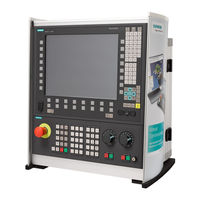
Siemens sinumerik fm-nc Manuals
Manuals and User Guides for Siemens sinumerik fm-nc. We have
3
Siemens sinumerik fm-nc manuals available for free PDF download: Programming Manual, Installation And Startup Manual
Siemens sinumerik fm-nc Programming Manual (598 pages)
Brand:
Siemens
| Category:
Controller
| Size: 3.55 MB
Table of Contents
SINUMERIK 840Di
2
Table of Contents
5
Preface
13
SINUMERIK 840DE (Export Version)
14
Flexible NC Programming
21
Spindles
23
Variables and Arithmetic Parameters
23
Variable Definition
25
Array Definition
30
Indirect Programming
36
Assignments
38
Arithmetic Operations/Functions
39
Comparison and Logic Operators
41
Priority of Operators
44
Possible Type Conversions
45
String Operations
46
Type Conversion
47
Chaining of Strings
49
Conversion to Lower/Upper Case
50
Length of String
51
Search for Character/String in String
51
Selection of a Substring
53
Selecting a Single Character
54
CASE Instruction
56
Control Structures
58
Program Coordination
63
Interrupt Routine
68
Axis Transfer, Spindle Transfer
76
NEWCONF: Setting Machine Data Active (as from SW 4.3)
80
WRITE: Write File (as from SW 4.3)
81
DELETE: Delete File (as from SW 4.3)
83
READ: Read Lines in File (as from SW 5.2)
84
ISFILE: File Available in User Memory NCK (as from SW 5.2)
87
CHECKSUM: Creation of a Checksum over an Array (< SW 5.2)
88
CHECKSUM: Creation of a Checksum over an Array (> SW 5.2)
88
Using Subprograms
92
Subprogram with SAVE Mechanism
94
Subprograms with Parameter Transfer
95
Calling Subprograms
99
Subprogram with Program Repetition
103
Modal Subprogram, MCALL
104
Calling the Subprogram Indirectly
105
Calling Subprogram with Path Specification and Parameters, PCALL
106
Suppressing Current Block Display, DISPLOF
107
Single Block Suppression, SBLOF, SBLON (SW 4.3 and Higher)
108
Executing an External Subprogram (SW 4.2 and Higher)
111
Cycles: Setting Parameters for User Cycles
113
Macros
118
File and Program Management
121
Overview
122
Program Memory
123
Program Memory
124
User Memory
128
Defining User Data
131
Defining Protection Levels for User Data (GUD)
135
Automatic Activation of Guds and Macs (SW 4.4 and Higher)
137
Protection Zones
139
Defining the Protection Zones CPROTDEF, NPROTDEF
140
Activating/Deactivating Protection Zones: CPROT, NPROT
144
Special Motion Commands
149
Approaching Coded Positions, CAC, CIC, CDC, CACP, CACN
150
Spline Interpolation
151
Compressor COMPON/COMPCURV
160
Polynomial Interpolation, POLY
163
Settable Path Reference, SPATH, UPATH (SW 4.3 and Higher)
169
Measurements with Touch Trigger Probe, MEAS, MEAW
174
Extended Measuring Function MEASA, MEAWA, MEAC (SW 4 and Higher, Option)
177
Special Functions for OEM Users
187
Programmable Motion End Criterion (SW 5.1 and Higher)
188
Programmable Servo Parameter Block (SW 5.1 and Higher)
189
Frames
191
Coordinate Transformation Via Frame Variables
192
Transformations
192
Frame Variables/Assigning Values to Frames
197
Coarse/Fine Offset
204
DRF Offset
205
External Zero Offset
206
Programming Preset Offset, PRESETON
207
Deactivating Frames
208
Frame Calculation from Three Measuring Points in the Area, MEAFRAME
209
NCU-Global Frames (SW 5 and Higher)
212
Channel-Specific Frames
213
Frames Active in the Channel
215
Transformations
219
Three, Four and Five-Axes Transformation: TRAORI
220
Programming the Tool Orientation
223
Tool Offsets
227
Orientation Axes Reference, ORIWKS, ORIMKS
228
Singular Positions and How They Are Handled
229
Orientation Axes (SW 5.2 and Higher)
230
Cartesian PTP Travel (SW 5.2 and Higher)
233
Milling Machining on Turned Parts: TRANSMIT
238
Cylinder Surface Transformation: TRACYL
241
Inclined Axis: TRAANG
247
Supplementary Conditions When Selecting a Transformation
251
Deactivate Transformation: TRAFOOF
253
Chained Transformations
254
Switchable Geometry Axes, GEOAX
257
Tool Offsets
263
Offset Memory
264
Tool Parameters
265
Language Commands for Tool Management
266
Online Tool Offset PUTFTOCF, PUTFTOC, FTOCON, FTOCOF
269
Maintain Tool Radius Compensation at Constant Level, CUTCONON (SW 4 and Higher)
275
Activate 3D Tool Tool Offsets
278
Tool Orientation
286
Free Assignment of D Numbers, Cutting Edge Number CE (as of SW 5)
291
Check D Numbers (CHKDNO)
292
Renaming D Numbers (GETDNO, SETDNO)
293
T Numbers for the Specified D Number (GETACTTD)
294
Set Final D Numbers to Invalid
295
Toolholder Kinematics
296
Path Traversing Behavior
301
Tangential Control TANG, TANGON, TANGOF
302
Coupled Motion TRAILON, TRAILOF
307
Curve Tables, CTABDEF, CTABEND, CTAB, CTABINV
311
Axial Leading Value Coupling, LEADON, LEADOF
319
Feed Characteristic, FNORM, FLIN, FCUB, FPO
325
Program Run with Preprocessing Memory, STARTFIFO, STOPFIFO, STOPRE
330
Repositioning on Contour, REPOSA, REPOSL, REPOSQ, REPOSH
332
Motion-Synchronous Action
337
Structure, Basic Information
339
Programming and Command Elements
341
Validity Range: Identification Number ID
342
Vocabulary Word
343
Actions
346
Overview of Synchronized Actions
348
Basic Modules for Conditions and Actions
350
Flags/Counters $Ac_Marker[N]
353
Special Real-Time Variables for Synchronized Actions
353
Timer Variable $Ac_Timer[N], as from SW 4
353
Synchronized Action Parameters $Ac_Param[N]
354
Access to R Parameters $Rxx
355
Oscillation
356
FIFO Variable $Ac_Fifo1[N]
357
Actions Within Synchronized Actions
359
Auxiliary Functions Output
359
Read-In Disable Set RDISABLE
360
Preprocessing Stop Cancel STOPREOF
361
Delete Distance-To-Go
362
Delete Distance-To-Go with Preparation, DELDTG, DELTG (Axis1
362
Polynomial Definition, FCTDEF, Block-Synchronized
364
Laser Power Control
366
Evaluation Function SYNFCT
367
Adaptive Control (Additive)
368
Adaptive Control (Multiplicative)
369
Clearance Control with Limited Compensation
370
Online Tool Offset FTOC
372
Positioning Movements
374
Position Axis POS
376
Start/Stop Axis MOV
376
Axial Feed: FA
377
SW Limit Switch
377
Axis Coordination
378
Set Actual Value
379
Spindle Motions
380
Coupled-Axis Motion: TRAILON, TRAILOF
381
Leading Value Coupling LEADON, LEADOF
382
Measurement
384
Wait Markers Set/Clear: SETM, CLEARM
384
Error Responses
385
Technology Cycles
386
Lock, Unlock, Reset: LOCK, UNLOCK, RESET
388
Cancel Synchronized Action: CANCEL
390
Supplementary Conditions
391
Oscillation
395
Asynchronous Oscillation
396
Oscillation Controlled Via Synchronized Actions
403
Punching and Nibbling
415
Activation, Deactivation
416
Language Commands
416
Use of M Commands
419
Automatic Path Segmentation
420
Path Segmentation for Path Axes
421
Path Segmentation for Single Axes
422
Programming Examples
424
Additional Functions
427
Axis Functions AXNAME, SPI, ISAXIS
428
Learn Compensation Characteristics: QECLRNON, QECLRNOF
429
Synchronized Spindle
431
Define Electronic Gear: EGDEF
441
EG: Electronic Gear (SW 5 and Higher)
441
Activate Electronic Gear
443
Deactivate Electronic Gear
445
Delete Definition of an Electronic Gear
446
Revolutional Feedrate (G95)/Electronic Gear (SW 5.2)
446
Extended Stopping and Retract (as of SW 5)
447
Response of EG at Power ON, RESET, Mode Change, Block Search
447
The Electronic Gear's System Variables
447
Drive-Independent Reactions
448
Possible Trigger Sources
449
Activation
450
Logic Gating Functions: Source/Reaction Operation
450
Drive-Independent Stop
451
Generator Operation/DC Link Backup
451
Drive-Independent Retract
452
Example: Using the Drive-Independent Reaction
453
Link Communication (SW 5.2 and Higher)
454
Axis Container (SW 5.2 and Higher)
457
Program Execution Time/Workpiece Counter (as from SW 5.2)
459
Program Runtime
459
Workpiece Counter
460
User Stock Removal Programs
463
Supporting Functions for Stock Removal
464
Tables
464
Contour Preparation: CONTPRON
465
Contour Decoding: CONTDCON (as of SW 5.2)
472
Intersection of Two Contour Elements: INTERSEC
476
Traversing a Contour Element from the Table: EXECTAB
478
Calculate Circle Data: CALCDAT
479
Tables
481
List of Instructions
483
Frames 1
509
List of System Variables
509
R Parameters
509
Toolholder Data
510
Channel-Specific Protection Zones
513
Tool Parameters
514
Monitoring Data for Tool Management
526
Monitoring Data for OEM Users
527
Tool-Related Data
527
Tool-Related Grinding Data
529
Magazine Location Data
530
Magazine Location Data for OEM Users
531
Magazine Description Data for Tool Management
532
Tool Management Magazine Description Data for OEM Users
533
Magazine Module Parameter
534
Measuring System Compensation Values
534
Quadrant Error Compensation
535
Interpolatory Compensation
536
NCK-Specific Protection Zones
537
System Data
538
Frames 2
539
Tool Data
539
G Groups
541
Programmed Values
541
Channel Statuses
543
Synchronized Actions
546
I/Os
548
NCU Link
549
Reading and Writing PLC Variables
549
Direct PLC I/O
550
Tool Management
551
Timers
552
Path Movement
553
Velocities
554
Spindles
555
Polynomial Values for Synchronized Actions
557
Channel Statuses
558
Positions
558
Encoder Limit Frequency
559
Indexing Axes
559
Encoder Values
560
Axial Measurement
561
Offsets
561
Axial Distances
562
Oscillation
563
Axial Velocities
564
Drive Data
565
Axis Statuses
566
Electronic Gear 1
567
Leading Value Coupling
568
Safety Integrated 1
569
Synchronized Spindle
569
Extended Stop and Retract
570
Axis Container
571
Electronic Gear 2
571
Safety Integrated 2
572
Appendix
575
Index
590
B Commands, Identifiers
591
Advertisement
Siemens sinumerik fm-nc Installation And Startup Manual (327 pages)
Brand:
Siemens
| Category:
Controller
| Size: 1.39 MB
Table of Contents
Table of Contents
9
1 General Preparations
15
Preconditions
15
Standard/Export Version
16
Configuration
16
2 2 Configuration
19
Mechanical Configuration
20
Overview
20
Mains Infeed Connection (OI, I/RF)
21
Mains Infeed Module
21
Ncu
22
PLC Start-Up
22
Electrical Configuration
23
General Configuration of SINUMERIK 840D System
23
Connection of Mains Infeed Module (U/E, I/RF)
25
Motor Connection
28
Encoder Connection
29
Connection of MMC100 and MMC102/103
30
Configuration of Components for Digitizing
32
3 Settings, MPI / OPI
35
Standard Configuration up to SW 3.1
35
Standard Configuration as from SW 3.2
40
Connection to OPI Bus
44
Connection to MPI Bus
45
Example of a Configuration of MCP and HHU Via OPI
46
Example of a Configuration of HHU Via MPI
47
Handheld Unit
52
Settings on the HHU for Software Version 4.X and Higher
53
Example: Connecting the HHU to the SINUMERIK 840D
55
Handheld Programming Unit
56
Interface Signals of the HPU
57
Standard Configuration of the HPU (Without MCP)
58
SINUMERIK 840D Installation and Start-Up Guide
59
Machine Control Panel (MCP)
66
Customer Operator Panel Interface
68
Second Machine Control Panel
69
Language Default
70
4 EMC / ESD Measures
73
Measures to Protect ESD-Sensitive Components
74
5 Power on and Power-Up
75
Start-Up Sequence
76
Power on and Power-Up
77
Power on
78
Power-Up
78
MMC100 - MMC102/103 Power-Up
80
Error During Control Power-Up (NC)
82
Drive System Power-Up
84
Machine Control Panel (MCP) Power-Up
84
MMC102/103 BIOS Setup
84
6 Assigning Parameters to the Control and the Plc Program
85
Machine and Setting Data
87
Handling Machine and Setting Data
89
Protection Level Concept
90
Function
92
Machine Data Masking Filter (SW 4.2 and Higher)
92
Saving the Filter Settings
95
Example of Start-Up Design Concept
96
Basic Settings
99
System Data
99
Memory Configuration
102
Dynamic RAM Memory
103
Static RAM Memory
104
Scaling Machine Data
106
Axes and Spindles
108
Description of the Axis Configuration
108
Drive Configuration (FDD, SLM, MSD)
111
Setting the Axis-Specific Setpoint/Actual Value Parameters
114
Drive Parameterization (FDD, MSD)
116
Parameterization of Incremental Measuring Systems
118
Parameterization of Absolute Measuring Systems (Endat Interface)
121
Drive Optimization
124
Axis Data
127
Velocity Matching (Axis)
129
Position Controller Data (Axis)
130
Monitoring Functions (Axis)
133
Reference Point Approach (Axis)
138
Spindle Data
140
Encoder Matching (Spindle)
142
Spindle Configuration
142
Speeds and Setpoint Adjustment for Spindle
144
Spindle Positioning
145
Spindle Synchronization
146
Spindle Monitoring
148
Example: Start-Up of NCK I/O Devices
150
General Information about Starting up Linear Motors
152
Linear Motors (1FN1 and 1FN3 Motors)
152
Start-Up: Linear Motor with One Primary Part
154
Start-Up: Linear Motors with 2 Identical Primary Parts
163
Mounting Dimensions
165
Temperature Sensors for 1FN1 and 1FN3 Motors
166
Measuring System
169
Parallel Connection of Linear Motors
172
Test Measurements on Linear Motor
174
AM / U/F Function
176
System Settings for Power Up, RESET and Part Program Start
177
7 PLC Start-Up
181
Overview of Organization Blocks, Function Blocks and Dbs
184
Alarm and Message Texts
185
Alarm and Message Texts
186
Alarm Text Files for MMC 102/103
188
Alarm Text Files for HPU
190
Syntax for Alarm Text Files
192
Properties of Alarm List
195
9 Axis and Spindle Dry Run
197
Preconditions
197
Axis Test Run
198
Testing the Spindle
200
10 Drive Optimization with Start-Up Tool
203
Instructions for Use
204
Installation
205
System Requirements
205
Starting the Program
206
Terminating the Program
206
Measuring Functions
207
Interface Signals Traverse Request and Motion Enable Drive Test
209
Aborting Measuring Functions
210
Frequency Response Measurement
211
Measurement of Torque Control Loop
211
Measurement of Speed Control Loop
212
Measurement of Position Control Loop
216
Graphic Display
219
Description
221
Gantry Axes (SW 5.1 and Higher)
221
Description
222
Trace Function (SW 4.2 and Higher)
222
Operation, Basic Display
223
Parameterization
224
Performing Measurement
227
Display Function
228
File Function
230
Print Graph
231
Analog Output (DAC)
233
10.10.1 Flow Chart for Self-Optimization
236
10.10.2 Input Options for Self-Optimization
240
11 Data Backup
245
Data Backup Via MMC 100
248
Data Backup Via MMC 102/103
254
Data Backup Via V24 on the MMC 102/103
255
Output of Drive Data Via V24 on MMC102/103
257
Output of Drive Data Via V24 on the MMC102/103
258
PLC Data Output Via V24 on MMC102/103
262
Output of the Series Start-Up File Via V24 on MMC102/103
263
Back up Hard Disk Via Norton Ghostr (SW 4.4 and Higher)
265
Saving User Data
268
Restore Data to Hard Disk
270
Several SW Versions on One MMC 103 (SW 5.2 and Higher)
272
Installing a Replacement Hard Disk (SW 4.4 and Higher)
274
Line Checksums (MD 11230 MD_FILE_STYLE)
281
Machine Data Numbers
282
Saving PLC Data
284
Machine/Setting Data
284
12 Software and Hardware Replacement
285
Software Update
285
Upgrading the MMC 100/100.2/101 Software
286
Upgrade of MMC 102/103 Software Version 4.X or Earlier
287
Upgrading the NC
288
Standard Upgrade
288
Series Start-Up Via NC Card (SW 4.4 and Higher)
289
SINUCOPY-FFS (SW 4.4 and Higher)
291
Hardware Replacement
296
Battery/Fan Replacement
296
2100 MMC
299
14 Miscellaneous
301
Tool Box Software Package
301
Content of Tool Box
301
Application of the Tool Box
301
Machine Data Access Via Part Program
302
A Abbreviations
306
B References
312
Siemens sinumerik fm-nc Programming Manual (327 pages)
Brand:
Siemens
| Category:
Controller
| Size: 2.09 MB
Table of Contents
Overview of SINUMERIK 840D/840Di/810D/Fm-NC Documentation (04.00)
2
SINUMERIK® Documentation
4
Printing History
4
Trademarks
4
Table of Contents
5
Structure of the Manual
8
Sinumerik 810D
8
Drilling Cycles and
9
Structure of Descriptions
9
Siemens AG 2000 All Rights Reserved
10
Proper Use
12
General
15
Milling Cycles
15
General Information
16
Overview of Cycles
16
Drilling Cycles, Drill Pattern Cycles, Milling Cycles and Turning Cycles
17
Overview of Cycles
17
Cycle Auxiliary Subroutines
18
Call and Return Conditions
19
Plane and Axis Assignments
19
Programming Cycles
19
Machine Data
20
Relevant Machine Data
20
Messages During Execution of a Cycle
21
Cycle Call and Parameter List
22
Cycle Call
23
Parameter List with Constant Values
23
Parameter List with Variables as Transfer Parameters
23
Incomplete Parameter List and Omission of Parameters
24
Use of Predefined Variables as Transfer Parameters
24
Expressions in the Parameter List
25
Function
25
Simulation of Cycles
25
Cycle Support in Program Editor (SW 4.3 and Later)
26
Overview of Important Files
27
Configuring Cycle Selection
28
Explanation of Syntax
29
Programming
29
Special Points Relating to MMC 102/103
29
Configuring Input Screenforms for Parameter Assignment
30
Cycle Parameterization
30
Programming Example
32
Configuring Help Displays
33
Configuring Tools (MMC 100 Only)
34
Loading to the Control
35
Sequence of Operations
35
Independence of Language
36
Operating the Cycles Support Function
37
Integrating User Cycles into the MMC 103 Simulation Function
38
Cycle Support in the Program Editor (SW 5.1 and Later)
39
Menus, Cycle Selection
39
New Functions in Input Screenforms
40
Contour Input Support
42
Operator Commands in the Help Display
42
Drilling Support
43
Programming Example Generated by Cycle Support
44
Milling Support
45
Turning Support
45
Retranslation
46
Drilling Cycles and Drilling Patterns
47
Drilling Cycles
48
Preconditions
50
Dwell Time Programming
51
Plane Definition
51
Spindle Programming
51
Drilling, Centering - CYCLE81
52
Description of Parameters
53
Further Notes
53
Drilling, Counterboring - CYCLE82
55
DTB (Dwell Time)
56
Deep-Hole Drilling - CYCLE83
57
Deep Hole Drilling with Chip Breaking (VARI=0)
60
Deep Hole Drilling
64
Rigid Tapping - CYCLE84
65
MPIT and PIT (as Thread Size and as Value)
67
POSS (Spindle Position)
67
Tapping with Compensating Chuck – CYCLE840
69
Thread with Encoder
74
Boring 1 – CYCLE85
75
Boring 2 – CYCLE86
78
Boring 3 – CYCLE87
82
Boring 4 – CYCLE88
85
Boring 5 - CYCLE89
87
Modal Call of Drilling Cycles
89
Drill Pattern Cycles
92
Preconditions
92
Row of Holes - HOLES1
93
Hole Circle - HOLES2
97
Dot Matrix - CYCLE801 (SW 5.3 and Later)
100
Milling Cycles
103
General Information
104
Preconditions
105
Cycle Setting Data
106
Machining Status Messages
106
Thread Cutting - CYCLE90
107
Sample Program
110
Elongated Holes on a Circle - LONGHOLE
113
Slots on a Circle - SLOT1
119
Circumferential Slot - SLOT2
127
Milling Rectangular Pockets - POCKET1
132
Milling Circular Pockets - POCKET2
136
Milling Rectangular Pockets - POCKET3
140
Motion Sequence When Finishing (VARI=X2)
144
Pocket
149
Milling Circular Pockets - POCKET4
150
Face Milling - CYCLE71
156
Path Milling - CYCLE72
162
Milling Rectangular Spigots - CYCLE76 (SW 5.3 and Later)
172
Milling Circular Spigots - CYCLE77 (SW 5.3 and Later)
177
Sequence of Motions for Roughing (_VARI=1)
178
Sequence of Motions for Finishing (_VARI=2)
179
Pocket Milling with Islands - CYCLE73, CYCLE74, CYCLE75 (SW 5.2 and Later)
181
Transfer Pocket Edge Contour - CYCLE74
182
Transfer Island Contour - CYCLE75
184
Contour Programming
185
Pocket Milling with Islands - CYCLE73
188
Edge/Base Finishing
190
Machine Residual Material
190
Rough Drill
190
Rough Drilling Sequence
191
Sequence for Roughing, Solid Machining (_VARI=XXX1)
192
Sequence of Motions for Finishing (_VARI=XXX3)
193
Turning Cycles
209
General Information
210
Preconditions
211
Contour Monitoring with Respect to Tool Clearance Angle
213
Grooving Cycle - CYCLE93
214
Undercut Cycle - CYCLE94
223
FORM (Definition)
225
Stock Removal Cycle - CYCLE95
227
MID (Infeed Depth)
230
FAL, FALZ and FALX (Final Machining Allowance)
231
FF1, FF2 and FF3 (Feedrate)
231
VARI (Machining Types)
232
DT and DAM (Dwell Time and Path Length)
233
_VRT (Lift)
233
Stock Removal Cycle
237
Thread Undercut - CYCLE96
239
Thread Cutting - CYCLE97
243
IANG (Infeed Angle)
247
NSP (Starting Point Offset)
247
NUMT (Number)
248
VARI (Machining Type)
248
Thread Cutting
250
Thread Chaining - CYCLE98
251
Thread Recutting (SW 5.3 and Later)
258
Extended Stock Removal Cycle - CYCLE950 (SW 5.3 and Later)
260
New Functions Compared to CYCLE95
263
Position Reached Prior to Cycle Start
263
Explanation of the Cycle Structure
271
Program Storage in the File System
271
Blank Updating
272
Error Messages and Error Handling
281
General Information
282
Troubleshooting in the Cycles
282
Overview of Cycle Alarms
283
Messages in the Cycles
288
Appendix
289
A Abbreviations
290
B Terms
299
C References
309
Index
321
Advertisement
Advertisement
Related Products
Siemens SINUMERIK828D
Siemens SINAMICS V90 PROFINET
Siemens SICAM TM
Siemens SIMOTION Series
Siemens SIMOVERT MASTERDRIVES SBP
Siemens SIMATIC S5 Series
Siemens SIMATIC PCS 7 CPU 410-5H
Siemens SIMODRIVE base line A
Siemens SIMATRIX
Siemens SITRANS S7-300
Siemens Categories
Industrial Equipment
Controller
Control Unit
Oven
Washer
More Siemens Manuals
Login
Sign In
OR
Sign in with Facebook
Sign in with Google
Upload manual
Upload from disk
Upload from URL