Sign In
Upload
Manuals
Brands
Siemens Manuals
Switch
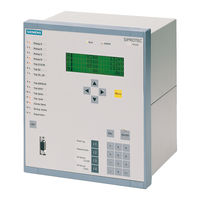
siprotec 7SA522
Siemens siprotec 7SA522 Manuals
Manuals and User Guides for Siemens siprotec 7SA522. We have
3
Siemens siprotec 7SA522 manuals available for free PDF download: User Manual, Manual
Siemens siprotec 7SA522 User Manual (628 pages)
Distance Protection
Brand:
Siemens
| Category:
Switch
| Size: 10.54 MB
Table of Contents
C53000-G1176-C119
2
Table of Contents
7
Table of Contents
8
Introduction
21
Overall Operation
22
Applications
24
Settings
25
Features
26
Scope of Functions
27
Hardware and Connections
31
Version of 7SA522 for Panel Flush Mounting (Cubicle Mounting)
32
Housing
32
Screw Terminal Connections
36
Connections to Plug-In Terminals
40
Connections to Optical Communication Interfaces
43
Connections to Electrical Communication Interfaces
44
Version of 7SA522 for Panel Surface Mounting
45
Housing
45
Screw Terminal Connections
48
Connections to Optical Communication Interfaces
48
Initial Inspections
51
Unpacking and Re-Packing
52
Inspections Upon Receipt
53
Inspection of Features and Ratings
53
Electrical Check
53
User Interface
55
Operation Using the Operator Control Panel
55
Operation Using DIGSI
58
Storage
63
Siprotec
65
General
66
Protection and Control
66
Communication
67
Settings
68
Operations
68
Oscillographic Fault Records
68
Operator Control Facilities
69
Operator Control Panel on Device
69
Measured Values
70
DIGSI ® 4 Tool
71
Information Retrieval
72
Annunciations
73
Measurements
75
Oscillographic Fault Records
77
Control
78
Manual Overwrite / Tagging
80
General about the Setting Procedures
81
Configuration of the Scope of Device Functions
84
Configuration of Inputs and Outputs (Configuration Matrix)
85
Programmable Logic CFC
88
Power System Data
90
Setting Groups
91
Settings
92
SIPROTEC ® 4 Devices
92
General Device Settings
93
Time Synchronization
94
Serial Interfaces
95
Passwords
97
Setting Groups
97
Configuration
99
Configuration of Functions
100
Settings
103
Configuration of the Binary Inputs and Outputs
105
Preparation
105
Structure and Operation of the Configuration Matrix
106
Control Commands for Switching Devices
110
Establishing Information Properties
112
Performing Configuration
119
Preset Configurations
125
Transferring Metering Values
128
Settings for Contact Chatter Blocking
130
Creating User Defined Functions with CFC
132
Establishing a Default Display
141
Serial Interfaces
142
Date and Time Stamping
146
Functions
149
General
150
Power System Data 1
155
Settings
160
Setting Groups
162
Information Overview
164
Settings
164
General Protection Data
165
Settings
175
Information Overview
176
Distance Protection
178
Earth Fault Recognition
178
Method of Operation
178
Setting of the Parameters for this Function
180
Calculation of the Impedances
181
Applying the Function Parameter Settings
187
Settings
189
Information Overview
190
Applying the Function Parameter Settings
198
Applying the Function Parameter Settings
209
Settings
213
Applying the Function Parameter Settings
219
Method of Operation
220
Applying the Function Parameter Settings
223
Settings
223
Information Overview
223
Distance Protection Teleprotection Schemes
225
Method of Operation
226
Direct Underreach Transfer Trip
228
Permissive Overreach Transfer Trip (POTT)
229
Unblocking with Z1B
232
Blocking Scheme
235
Transient Blocking
238
Measures for Weak and Zero Infeed
239
Settings
240
Applying the Function Parameter Settings
240
Settings
243
Method of Operation
245
Earth Fault Protection in Earthed Systems
245
Applying the Function Parameter Settings
251
Settings
257
Information Overview
260
Earth Fault Protection Teleprotection Schemes
261
Method of Operation
262
Directional Unblocking Scheme
264
Directional Blocking Scheme
266
Transient Blocking
267
Measures for Weak or Zero Infeed
268
Applying the Function Parameter Settings
270
Settings
273
Information Overview
273
Weak-Infeed Tripping
274
Applying the Function Parameter Settings
276
Settings
277
External Direct and Remote Tripping
278
Applying the Function Parameter Settings
279
Overcurrent Protection
280
Method of Operation
281
Applying the Function Parameter Settings
287
Settings
294
Information Overview
295
High-Current Switch-On-To-Fault Protection
297
Applying the Function Parameter Settings
298
Automatic Reclosure Function
299
Function Description
300
Setting the Function Parameters
316
Settings
322
Information Overview
325
Synchronism and Voltage Check (Dead-Line / Dead-Bus Check)
329
Method of Operation
329
Applying the Function Parameter Settings
332
Settings
336
Information Overview
337
Overvoltage Protection
339
Method of Operation
339
Applying the Function Parameter Settings
340
Settings
342
Information Overview
342
Fault Location
343
Method of Operation
343
Applying the Function Parameter Setting
345
Settings
346
Information Overview
346
Circuit Breaker Failure Protection
348
Method of Operation
348
Applying the Function Parameter Settings
359
Settings
362
Information Overview
362
Monitoring Functions
364
Method of Operation
364
Hardware-Monitoring
364
Software-Monitoring
366
Monitoring of the External Instrument Transformer Circuits
366
Response to Failures
372
Applying the Function Parameter Settings
374
Trip Circuit Supervision
376
Settings
376
Information Overview
377
Function Control
379
Detection of Line Energization
379
Processing of the Circuit Breaker Position
380
Overall Fault Detection Logic of the Device
383
Overall Tripping Logic of the Device
385
Circuit Breaker Trip Test
390
Setting Parameters
391
Settings
392
Information Overview
393
Supplementary Functions
394
Processing of Messages
394
Operational Measurement and Energy Metering
395
Data Storage for Fault Recording
397
Applying the Function Parameter Settings
397
Settings
398
Information Overview
399
Processing of Commands
401
Types of Commands
401
Steps in the Command Sequence
402
Interlocking
403
Interlocked/Non-Interlocked Switching
403
Recording and Acknowledgement of Commands
406
Control During Operation
409
Read-Out of Information
410
Event Log (Operating Messages)
413
Trip Log (Fault Messages)
414
Saving and Erasing the Messages
417
General Interrogation
418
Switching Statistics
419
Resetting and Setting the Switching Statistics
420
Measured Values
421
Setting and Retrieval of User Defined Set-Points
425
Retrieval and Resetting of User Defined Pulse Metered Values (PMV)
427
Fault Records
428
Saving the Fault Records
429
Control of Device Functions
430
Changeover of Setting Groups
435
Test Messages to the System (SCADA) Interface During Test Operation
437
Circuit Breaker Test Function
440
Control of Switchgear
444
Display Equipment Position and Control
445
Manual Overwriting
448
Set Status
449
Interlocking
451
Tagging
452
Switching Authority
453
Switching Mode
454
Control Messages
455
Installation and Commissioning
457
Mounting and Connections
458
Termination Variants
462
Hardware Modifications
467
Jumpers on the Printed Circuit Boards
468
Checking the Connections
476
Power Plant Connections
478
Commissioning
480
Current, Voltage, and Phase Rotation Checks
481
Directional Checks with Load Current
482
Polarity Check for the Voltage Input U4
483
Measuring the Operating Time of the Circuit Breaker
488
Testing of the Teleprotection System
489
Teleprotection with Earth Fault Protection
491
Signal Transmission for the Overvoltage Protection
492
Protection
493
Checking the Binary Inputs and Outputs
494
Tests for the Circuit Breaker Failure Protection
496
Testing User-Defined Functions
498
Triggering Oscillographic Recordings
499
Generate Indications
500
Final Preparation of the Device
502
Routine Checks and Maintenance
503
General
504
Routine Checks
505
Maintenance
506
Troubleshooting
509
Corrective Action / Repairs
511
Return
515
Technical Data
517
General Device Data
518
Binary Inputs and Outputs
519
Communications Interfaces
520
Electrical Tests
522
Mechanical Stress Tests
524
Climatic Stress Tests
525
Certifications
526
Power Swing Supplement
528
Distance Protection Teleprotection Schemes
529
Earth Fault Protection in Earthed Systems
530
Earth Fault Protection Teleprotection Schemes
536
Overcurrent Protection
537
High-Current Switch-On-To-Fault Protection
539
Synchronism and Voltage Check (Dead-Line / Dead-Bus Check)
540
Overvoltage Protection
541
Fault Location
542
Monitoring Functions
543
Supplementary Functions
544
Dimensions
546
Ordering Information and Accessories
550
Accessories
552
General Diagrams
554
Panel Surface Mounting
557
Connection Examples
562
Preset Configurations
569
Protocol Dependent Functions
572
List of Information
573
Advertisement
Siemens siprotec 7SA522 Manual (607 pages)
Distance Protection
Brand:
Siemens
| Category:
Protection Device
| Size: 9.33 MB
Table of Contents
C53000-G1176-C155
3
Introduction
17
Overall Operation
18
Application Scope
22
Characteristics
25
Functions
31
General
32
Settings
35
Device
37
Setting Notes
38
Power System Data 1
40
Settings
44
Setting Group Changeover
46
Information List
47
Settings
57
Information List
58
Oscillographic Fault Records
60
Settings
61
Distance Protection
62
Calculation of the Impedances
65
Setting Notes
72
Settings
76
Information List
77
Distance Protection with Quadrilateral Characteristic (Optional)
80
Setting Notes
86
Settings
90
Distance Protection with MHO Characteristic (Optional)
92
Setting Notes
97
Settings
101
Tripping Logic of the Distance Protection
102
Setting Notes
107
Power Swing Detection (Optional)
108
Setting Notes
113
Settings
114
Protection Data Interfaces and Communication Topology (Optional)
115
Setting Notes
118
Settings
122
Remote Signals Via Protection Data Interface (Optional)
124
Information List
125
Teleprotection for Distance Protection
127
Method of Operation
128
Permissive Underreach Transfer Trip with Zone Acceleration Z1B (PUTT)
129
Direct Underreach Transfer Trip
131
Permissive Overreach Transfer Trip (POTT)
132
Directional Unblocking Scheme
136
Directional Blocking Scheme
140
Transient Blocking
143
Measures for Weak and Zero Infeed
144
Setting Notes
146
Settings
149
Earth Fault Overcurrent Protection in Earthed Systems (Optional)
151
Setting Notes
163
Settings
172
Information List
175
Teleprotection for Earth Fault Overcurrent Protection (Optional)
176
Directional Comparison Pickup
177
Directional Unblocking Scheme
181
Directional Blocking Scheme
185
Transient Blocking
188
Measures for Weak or Zero Infeed
189
Setting Notes
190
Settings
194
Weak-Infeed Tripping
196
Setting Notes
199
Setting Notes
202
Settings
203
Information List
204
External Direct and Remote Tripping
206
Setting Notes
207
Overcurrent Protection
208
Method of Operation
209
Setting Notes
215
Settings
220
Information List
222
Instantaneous High-Current Switch-On-To-Fault Protection (SOTF)
224
Setting Notes
225
Information List
226
Automatic Reclosure Function (Optional)
227
Method of Operation
228
Setting Notes
245
Settings
254
Information List
256
Synchronism and Voltage Check (Optional)
259
Setting Notes
263
Settings
268
Information List
269
Undervoltage and Overvoltage Protection (Optional)
271
Undervoltage Protection
276
Setting Notes
280
Settings
284
Information List
286
Frequency Protection (Optional)
288
Setting Notes
290
Settings
292
Information List
293
Fault Locator
294
Setting Notes
296
Settings
297
Circuit Breaker Failure Protection (Optional)
299
Setting Notes
309
Settings
312
Information List
313
Monitoring Function
314
Software Monitoring
316
Malfunction Responses
321
Setting Notes
322
Settings
324
Information List
325
Setting Notes
328
Function Control and Circuit Breaker Testing
330
Detection of the Circuit Breaker Position
333
Open Pole Detector
336
Pickup Logic for the Entire Device
337
Tripping Logic of the Entire Device
338
Setting Notes
344
Setting Notes
345
Auxiliary Functions
346
Statistics
349
Function Description
350
Measurement
351
Information List
353
Demand Measurement Setup
355
Information List
356
Information List
357
Set Points (Measured Values)
358
Limit Value Monitoring
359
Energy
360
Command Processing
362
Sequence in the Command Path
363
Switchgear Interlocking
364
Information List
367
Process Data
368
Information List
369
Mounting and Commissioning
371
Mounting and Connections
372
Hardware Modifications
376
Disassembly
378
Switching Elements on Printed Circuit Boards
380
Interface Modules
387
Reassembly
391
Rack Mounting and Cubicle Mounting
393
Panel Surface Mounting
395
Checking Connections
396
Checking the Protection Data Communication
398
Checking System Connections
399
Commissioning
401
Test Mode / Transmission Block
402
Testing the System Interface
403
Checking the Binary Inputs and Outputs
405
Checking the Communication Topology
407
Tests for Circuit Breaker Failure Protection
411
Current, Voltage, and Phase Rotation Testing
413
Direction Check with Load Current
414
Polarity Check for the Voltage Input U4
415
Polarity Check for the Current Input I4
418
Measuring the Operating Time of the Circuit Breaker
421
Testing of the Teleprotection System with Distance Protection
422
Testing of the Signal Transmission with Earth-Fault Protection
424
Check of the Signal Transmission for Internal and External Remote Tripping
426
Testing User-Defined Functions
427
Triggering Oscillographic Recordings for Test
428
Final Preparation of the Device
430
Technical Data
431
General
432
Auxiliary Voltage
433
Communication Interfaces
435
Electrical Tests
439
Mechanical Stress Tests
441
Climatic Stress Tests
442
Certifications
443
Distance Protection
444
Power Swing Detection (Optional)
447
Teleprotection for Distance Protection
448
Earth Fault Overcurrent Protection in Earthed Systems (Optional)
450
Teleprotection for Earth Fault Overcurrent Protection (Optional)
459
Weak-Infeed Tripping (Classic)
460
Weak-Infeed Tripping (French Specification)
461
Protection Data Interfaces and Communication Topology (Optional)
462
External Direct and Remote Tripping
463
Time Overcurrent Protection
464
Instantaneous High-Current Switch-Onto-Fault Protection
467
Automatic Reclosure Function (Optional)
468
Synchronism and Voltage Check (Optional)
469
Undervoltage and Overvoltage Protection (Optional)
471
Frequency Protection (Optional)
474
Fault Locator
475
Circuit Breaker Failure Protection (Optional)
476
Monitoring Function
477
Transmission of Binary Information (Optional)
479
User Defined Functions (CFC)
481
Auxiliary Functions
484
Dimensions
486
A Appendix
490
A.1.2 Accessories
495
A.2 Terminal Assignments
498
A.2.2 Housing for Panel Surface Mounting
503
A.3 Connection Examples
512
A.3.2 Voltage Transformer Examples
516
A.4 Default Settings
519
A.4.2 Binary Inputs
520
A.4.4 Function Keys
521
A.4.5 Default Display
522
A.4.6 Pre-Defined CFC Charts
523
A.5 Protocol-Dependent Functions
527
A.6 Functional Scope
528
A.7 Settings
530
A.8 Information List
546
A.9 Group Alarms
584
A.10 Measured Values
585
Literature
591
Glossary
593
Index
601
Siemens siprotec 7SA522 Manual (94 pages)
Input/Output unit, Bay control unit, Communication module, PROFIBUS-DP Communication profile
Brand:
Siemens
| Category:
Protection Device
| Size: 0.65 MB
Table of Contents
Preface
3
Revision Index
7
Table of Contents
9
1 PROFIBUS Communication Modules
11
Communication Module Types and Hardware Revisions
12
Communication Module Types
12
Hardware Revisions
12
Compatibility of the Communication Module Hardware with PROFIBUS-DP Firmware Versions and Mapping Files
13
Display of Module-Specific Information at the SIPROTEC Device
15
Block 1: Status and Parameters of the PROFIBUS-DP Slave
17
Block 2: Firmware Versions and Mapping File
19
Block 3: Module Hardware Information and Boot Firmware Version
20
Block 4: OLM Information
21
Block 5: Status of the Event List Via PROFIBUS-DP
24
2 Parameters and Properties
25
Bus Specific Parameters
26
PROFIBUS-DP Settings
26
Configuration of the Fibre-Optical Interface
28
Event List Settings
31
PROFIBUS-DP Configuration Data
31
Execution of Switching Operations Via PROFIBUS-DP
32
Command Output Modes
32
Transformer Tap Change Commands
33
Behaviour under Special Operating Conditions
33
Response in the Event of Disturbed Communication to the PROFIBUS-DP Master
34
Communication Interruption
34
Signalling of Line-Breaks in a Redundant Fibre-Optical Ring
35
Annunciations to the PROFIBUS-DP Master
37
Event List Via PROFIBUS-DP (Sequence of Events Recorder)
38
Properties of the Event List
39
Structure of a PROFIBUS-DP Telegram with Event List
40
Telegram in Input Direction
40
Telegram in Output Direction
42
Handshake Mechanism
43
3 Data Type Definitions
45
Single-Point Indication (SP, Input)
46
Single Command (SC, Output)
47
Double-Point Indication (DP, Input) / Double Command (DC, Output)
48
Measured Value (Signed Integer)
49
Measured Value (Float)
50
Metered Measurand (Unsigned Long)
51
Transformer Tap Change Command (TC)
52
Transformer Tap Position Indication (TM)
53
Message Block for Event List Via PROFIBUS-DP
54
4 PROFIBUS-DP - Parameterization in DIGSI
57
Interface Selection and Mapping Files
58
Standard Mappings 3-1 to 3-N
58
Compatibility with Standard Mappings of Previous Versions
59
Interface Selection and Mapping Selection in DIGSI 4.21
59
Interface Selection and Mapping Selection in DIGSI 4.3 or Higher
63
Customization of the Allocations
66
Scaling of Measured Values
70
Measurement Conversion
70
Number Representation Depending on the Parameterization
71
Parameterization in DIGSI
73
Time Synchronization
75
PROFIBUS-DP Master
75
Parameterization in DIGSI
77
Using SFC14 and SFC15 in STEP7
79
5 Technical Data
83
Connection Via the PSE Module
84
Connection Via the PSO Module
86
Glossary
89
Index
91
Advertisement
Advertisement
Related Products
Siemens 7-FSV-500
Siemens 7ML5735
Siemens 7ML5731
Siemens 7ML5734
Siemens 7XV5550-0xA00 Series
Siemens 7XV5655-0BA00
Siemens 7XV75
Siemens 7ML700
Siemens 7ML703
Siemens 7ML5725
Siemens Categories
Industrial Equipment
Controller
Control Unit
Oven
Washer
More Siemens Manuals
Login
Sign In
OR
Sign in with Facebook
Sign in with Google
Upload manual
Upload from disk
Upload from URL