Sign In
Upload
Manuals
Brands
Siemens Manuals
Relays
SIPROTEC 7SD610
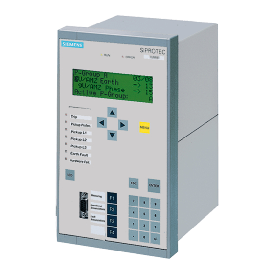
Siemens SIPROTEC 7SD610 Manuals
Manuals and User Guides for Siemens SIPROTEC 7SD610. We have
3
Siemens SIPROTEC 7SD610 manuals available for free PDF download: Manual, User Manual
Siemens SIPROTEC 7SD610 Manual (448 pages)
Brand:
Siemens
| Category:
Relays
| Size: 9.13 MB
Table of Contents
Functions
3
Technical Data
4
C53000-G1176-C145
6
Table of Contents
9
1 Introduction
17
Overall Operation
18
Application Scope
21
Characteristics
24
2 Functions
29
General
30
Functional Scope
30
Configuration of the Scope of Functions
30
Setting Notes
31
Settings
33
General Power System Data (Power System Data 1)
34
Setting Notes
34
Settings
39
Change Group
40
Purpose of the Setting Groups
40
Setting Notes
41
Settings
41
Information List
41
General Protection Data (Power System Data 2)
42
Setting Notes
42
Settings
47
Information List
48
Protection Data Interfaces and Protection Data Topology
50
Functional Description
50
Protection Data Topology / Protection Data Communication
50
Operating Modes of the Differential Protection
53
Mode: Log out Device
53
Differential Protection Test Mode
55
Differential Protection Commissioning Mode
57
Protection Data Interfaces
59
Setting Notes
59
Settings
61
Information List
62
Differential Protection Topology
63
Setting Notes
63
Settings
64
Information List
64
Differential Protection
65
Function Description
65
Setting Notes
72
Settings
75
Information List
76
Breaker Intertrip and Remote Tripping
78
Function Description
78
Setting Notes
80
Settings
80
Information List
81
Restricted Earth Fault Protection (Optional)
82
Application Examples
82
Functional Description
83
Setting Notes
88
Settings
89
Information List
89
Direct Local Trip
90
Method of Operation
90
Setting Notes
90
Settings
91
Information List
91
Transmission of Binary Commands and Messages
92
Function Description
92
Information List
93
Instantaneous High-Current Switch-Onto-Fault Protection (SOTF)
95
Function Description
95
Setting Notes
97
Settings
99
Information List
99
Backup Time Overcurrent Protection
100
General
100
Function Description
100
Setting Notes
114
Settings
120
Information List
123
Automatic Reclosure Function (Optional)
125
Function Description
125
Setting Notes
141
Settings
149
Information List
151
Undervoltage and Overvoltage Protection (Optional)
153
Overvoltage Protection
153
Undervoltage Protection
160
Setting Notes
163
Settings
167
Information List
169
Frequency Protection (Optional)
172
Functional Description
172
Setting Notes
175
Settings
176
Information List
177
Circuit Breaker Failure Protection
178
Function Description
178
Setting Notes
190
Settings
193
Information List
194
Thermal Overload Protection
195
Method of Operation
195
Setting Notes
196
Settings
198
Information List
198
Monitoring Functions
199
Measurement Supervision
199
Hardware Monitoring
199
Software Monitoring
201
Measurement Circuit Monitoring
201
Monitoring the Phase Angle of the Positive Sequence Power
210
Fault Reactions
212
Setting Notes
214
Settings
216
Information List
217
Trip Circuit Supervision
218
Function Description
218
Setting Notes
221
Settings
221
Information List
221
Function Control and Circuit Breaker Test
222
Function Control
222
Line Energization Recognition
222
Detection of the Circuit Breaker Position
226
Open Pole Detector
228
Pickup Logic of the Entire Device
230
Tripping Logic of the Entire Device
231
Circuit Breaker Test
236
Functional Description
236
Information List
237
Device
237
Trip-Dependent Indications
237
Switching Statistics
238
Setting Notes
239
Settings
239
Information List
239
EN100-Modul 1
241
Setting Notes
241
Information List
241
Function Description
242
Commissioning Aid
242
Additional Functions
243
Setting Notes
244
Processing of Messages
245
Function Description
245
Statistics
248
Function Description
248
Information List
249
Measurement During Operation
250
Function Description
250
Information List
253
Differential Protection Values
254
Measured Values of Differential Protection
254
Functional Description
254
Remote Measured Values
255
Function Description
255
Measured Values Constellation
255
Oscillographic Fault Records
256
Settings
256
Setting Notes
257
Energy
257
Energy Metering
257
Information List
258
Control Authorization
259
Type of Commands
259
Command Processing
260
Sequence in the Command Path
260
Interlocking
261
Information List
264
Control Device
264
Process Data
265
Method of Operation
265
Information List
266
Protocol
266
3 Mounting and Commissioning
269
Mounting and Connections
270
Configuration Information
270
Hardware Modifications
274
General
274
Disassembly
275
Switching Elements on Printed Circuit Boards
277
Interface Modules
282
Reassembly
286
Mounting
286
Panel Flush Mounting
286
Rack and Cubicle Mounting
287
Panel Mounting
288
Checking Connections
289
Checking Data Connections of Serial Interfaces
289
Checking the Protection Data Communication
292
Checking the System Connections
293
Commissioning
295
Test Mode / Transmission Block
296
Test Time Synchronisation Interface
296
Testing the System Interface
297
Checking the Switching States of the Binary Inputs/Outputs
299
Checking the Protection Data Topology
302
Checking for Breaker Failure Protection
308
Checking the Instrument Transformer Connections of One Line End
310
Checking the Instrument Transformer Connections with Two Line Ends
311
Check of the Signal Transmission for Internal and External Remote Tripping
317
Testing User-Defined Functions
318
Trip and Close Test with the Circuit Breaker
318
Trip / Close Tests for the Configured Operating Devices
318
Triggering Oscillographic Recording for Test
319
Final Preparation of the Device
320
4 Technical Data
321
General
322
Analog Inputs
322
Auxiliary Voltage
323
Binary Inputs and Outputs
324
Communication Interfaces
326
Electrical Tests
330
Mechanical Tests
331
Climatic Stress Tests
332
Deployment Conditions
333
Constructive Versions
333
Protection Data Interfaces and Differential Protection Topology
334
Differential Protection
338
Restricted Earth Fault Protection
340
Breaker Intertrip and Remote Tripping- Direct Local Trip
341
Transmission of Binary Information (Optional)
342
Instantaneous High-Current Switch-Onto-Fault Protection (SOTF)
343
Backup Time Overcurrent Protection
344
Automatic Reclosure (Optional)
351
Voltage Protection (Optional)
352
Frequency Protection (Optional)
355
Circuit Breaker Failure Protection (Optional)
356
Thermal Overload Protection
357
Monitoring Functions
359
User Defined Functions (CFC)
360
Auxiliary Functions
364
Dimensions
367
Housing for Panel Flush Mounting or Cubicle Installation
367
Panel Surface Mounting
368
Appendix
369
Ordering Information and Accessories
370
Ordering Information
370
Ordering Code (MLFB)
370
Accessories
373
A.1.2 Accessories
373
Terminal Assignments
377
Housing for Panel Flush and Cubicle Mounting
377
A.2 Terminal Assignments
377
Housing for Panel Surface Mounting
378
Connection Examples
379
Current Transformer Connection Examples
379
A.3 Connection Examples
379
Voltage Transformer Examples
381
Default Settings
382
Leds
382
Binary Input
382
Binary Output
382
A.4 Default Settings
382
Function Keys
383
Default Display
383
A.4.4 Function Keys
383
Pre-Defined CFC Charts
384
Protocol-Dependent Functions
385
Functional Scope
386
A.6 Functional Scope
386
Settings
387
A.7 Settings
387
Information List
397
A.8 Information List
397
Group Alarms
424
A.9 Group Alarms
424
Measured Values
425
A.10 Measured Values
425
Literature
429
Glossary
431
Index
443
Advertisement
Siemens SIPROTEC 7SD610 User Manual (438 pages)
Differential Protection
Brand:
Siemens
| Category:
Relays
| Size: 8.85 MB
Table of Contents
Mounting and Commissioning 3
3
Table of Contents
7
1 Introduction
15
Overall Operation
16
Application Scope
19
Characteristics
22
2 Functions
27
General
28
Functional Scope
28
Configuration of the Scope of Functions
28
Setting Notes
29
Settings
31
General Power System Data (Power System Data 1)
32
Setting Notes
32
Settings
38
Change Group
39
Purpose of the Setting Groups
39
Setting Notes
39
Settings
40
Information List
40
General Protection Data (Power System Data 2)
40
Setting Notes
40
Settings
46
Information List
47
Protection Data Interfaces and Protection Data Topology
49
Functional Description
49
Protection Data Topology / Protection Data Communication
49
Operating Modes of the Differential Protection
51
Mode: Log out Device
51
Differential Protection Test Mode
53
Differential Protection Commissioning Mode
55
Protection Data Interfaces
56
Setting Notes
56
Settings
58
Information List
59
Differential Protection Topology
59
Setting Notes
59
Settings
61
Information List
61
Differential Protection
62
Function Description
62
Setting Notes
70
Settings
73
Information List
74
Breaker Intertrip and Remote Tripping
76
Function Description
76
Setting Notes
77
Settings
78
Information List
78
Restricted Earth Fault Protection (Optional)
80
Application Examples
80
Functional Description
81
Setting Notes
86
Settings
87
Information List
88
Direct Local Trip
89
Method of Operation
89
Setting Notes
89
Settings
90
Information List
90
Direct Remote Trip and Transmission of Binary Information
91
Function Description
91
Information List
92
Instantaneous High-Current Switch-Onto-Fault Protection (SOTF)
93
Function Description
93
Setting Notes
94
Settings
95
Information List
96
Backup Time Overcurrent Protection
97
General
97
Function Description
97
Setting Notes
111
Settings
117
Information List
120
Automatic Reclosure Function (Optional)
122
Function Description
122
Setting Notes
138
Settings
146
Information List
149
Undervoltage and Overvoltage Protection (Optional)
151
Overvoltage Protection
151
Undervoltage Protection
158
Setting Notes
161
Settings
166
Information List
168
Frequency Protection (Optional)
171
Functional Description
171
Setting Notes
173
Settings
175
Information List
176
Circuit Breaker Failure Protection
177
Function Description
177
Setting Notes
188
Settings
192
Information List
193
Thermal Overload Protection
194
Method of Operation
194
Setting Notes
195
Settings
197
Information List
197
Monitoring Functions
198
Measurement Supervision
198
Hardware Monitoring
198
Software Monitoring
200
Measurement Circuit Monitoring
200
Monitoring the Phase Angle of the Positive Sequence Power
207
Fault Reactions
210
Setting Notes
212
Settings
213
Information List
214
Trip Circuit Supervision
215
Function Description
215
Setting Notes
219
Settings
219
Information List
219
Function Control and Circuit Breaker Test
220
Function Control
220
Line Energisation Recognition
220
Detection of the Circuit Breaker Position
224
Open Pole Detector
226
Pickup Logic of the Entire Device
228
Tripping Logic of the Entire Device
229
Circuit Breaker Test
234
Functional Description
234
Information List
235
Device
235
Trip-Dependent Indications
236
Spontaneous Indications on the Display
236
Switching Statistics
236
Setting Notes
237
Settings
237
Information List
237
EN100-Modul 1
239
Function Description
239
Setting Notes
239
Information List
239
Additional Functions
240
Commissioning Aid
240
Function Description
240
Setting Notes
242
Processing of Messages
242
Function Description
242
Statistics
246
Function Description
246
Information List
247
Measurement During Operation
247
Function Description
247
Information List
249
Differential Protection Values
250
Measured Values of the Differential Protection
250
Information List
251
Remote Measured Values
251
Function Description
251
Measured Values Constellation
252
Functional Description
252
Oscillographic Fault Records
252
Function Description
252
Setting Notes
253
Settings
254
Information List
254
Energy
254
Energy Metering
254
Setting Notes
255
Information List
255
Command Processing
256
Control Authorization
256
Type of Commands
256
Sequence in the Command Path
257
Interlocking
258
Information List
261
Control Device
261
Process Data
262
Method of Operation
262
Information List
263
Protocol
263
3 Mounting and Commissioning
265
Mounting and Connections
266
Configuration Information
266
Hardware Modifications
270
General
270
Disassembly
271
Switching Elements on Printed Circuit Boards
273
Interface Modules
279
Reassembly
283
Mounting
283
Panel Flush Mounting
283
Rack and Cubicle Mounting
284
Panel Mounting
285
Checking Connections
286
Checking Data Connections of Serial Interfaces
286
Checking the Protection Data Communication
288
Checking the System Connections
289
Commissioning
292
Test Mode / Transmission Block
293
Test Time Synchronisation Interface
293
Testing the System Interface
294
Checking the Switching States of the Binary Inputs/Outputs
296
Checking the Protection Data Topology
298
Checking for Breaker Failure Protection
305
Checking the Instrument Transformer Connections of One Line End
307
Checking the Instrument Transformer Connections of Two Line Ends
309
Check of the Signal Transmission for Internal and External Remote Tripping
315
Testing User-Defined Functions
316
Trip and Close Test with the Circuit Breaker
316
Trip / Close Tests for the Configured Operating Devices
316
Triggering Oscillographic Recording for Test
317
Final Preparation of the Device
318
4 Technical Data
319
General
320
Analog Inputs
320
Auxiliary Voltage
321
Binary Inputs and Outputs
322
Communication Interfaces
323
Electrical Tests
327
Mechanical Tests
328
Climatic Stress Tests
329
Deployment Conditions
330
Constructive Versions
330
Protection Data Interfaces and Differential Protection Topology
331
Differential Protection
333
Restricted Earth Fault Protection
335
Breaker Intertrip and Remote Tripping- Direct Local Trip
336
Transmission of Binary Information (Optional)
337
Instantaneous High-Current Switch-Onto-Fault Protection (SOTF)
338
Backup Time Overcurrent Protection
339
Automatic Reclosure (Optional)
346
Voltage Protection (Optional)
347
Frequency Protection (Optional)
350
Circuit Breaker Failure Protection (Optional)
351
Thermal Overload Protection
352
Monitoring Functions
354
User Defined Functions (CFC)
356
Auxiliary Functions
360
Dimensions
363
Housing for Panel Flush Mounting or Cubicle Installation
363
Panel Surface Mounting
364
Appendix
365
Ordering Information and Accessories
366
Ordering Information
366
Ordering Code (MLFB)
366
Accessories
368
A.1.2 Accessories
368
Terminal Assignments
372
Housing for Panel Flush and Cubicle Mounting
372
A.2 Terminal Assignments
372
Housing for Panel Surface Mounting
373
Connection Examples
374
Current Transformer Connection Examples
374
A.3 Connection Examples
374
Voltage Transformer Examples
376
Default Settings
377
Leds
377
Binary Input
377
A.4 Default Settings
377
Binary Output
378
Function Keys
378
Default Display
378
A.4.3 Binary Output
378
Pre-Defined CFC Charts
379
Protocol-Dependent Functions
380
Functional Scope
381
A.6 Functional Scope
381
Settings
382
A.7 Settings
382
Information List
392
A.8 Information List
392
Group Alarms
416
A.9 Group Alarms
416
Measured Values
417
A.10 Measured Values
417
Literature
421
Glossary
423
Index
433
Siemens SIPROTEC 7SD610 Manual (94 pages)
Input/Output unit, Bay control unit, Communication module, PROFIBUS-DP Communication profile
Brand:
Siemens
| Category:
Protection Device
| Size: 0.65 MB
Table of Contents
Preface
3
Revision Index
7
Table of Contents
9
1 PROFIBUS Communication Modules
11
Communication Module Types and Hardware Revisions
12
Communication Module Types
12
Hardware Revisions
12
Compatibility of the Communication Module Hardware with PROFIBUS-DP Firmware Versions and Mapping Files
13
Display of Module-Specific Information at the SIPROTEC Device
15
Block 1: Status and Parameters of the PROFIBUS-DP Slave
17
Block 2: Firmware Versions and Mapping File
19
Block 3: Module Hardware Information and Boot Firmware Version
20
Block 4: OLM Information
21
Block 5: Status of the Event List Via PROFIBUS-DP
24
2 Parameters and Properties
25
Bus Specific Parameters
26
PROFIBUS-DP Settings
26
Configuration of the Fibre-Optical Interface
28
Event List Settings
31
PROFIBUS-DP Configuration Data
31
Execution of Switching Operations Via PROFIBUS-DP
32
Command Output Modes
32
Transformer Tap Change Commands
33
Behaviour under Special Operating Conditions
33
Response in the Event of Disturbed Communication to the PROFIBUS-DP Master
34
Communication Interruption
34
Signalling of Line-Breaks in a Redundant Fibre-Optical Ring
35
Annunciations to the PROFIBUS-DP Master
37
Event List Via PROFIBUS-DP (Sequence of Events Recorder)
38
Properties of the Event List
39
Structure of a PROFIBUS-DP Telegram with Event List
40
Telegram in Input Direction
40
Telegram in Output Direction
42
Handshake Mechanism
43
3 Data Type Definitions
45
Single-Point Indication (SP, Input)
46
Single Command (SC, Output)
47
Double-Point Indication (DP, Input) / Double Command (DC, Output)
48
Measured Value (Signed Integer)
49
Measured Value (Float)
50
Metered Measurand (Unsigned Long)
51
Transformer Tap Change Command (TC)
52
Transformer Tap Position Indication (TM)
53
Message Block for Event List Via PROFIBUS-DP
54
4 PROFIBUS-DP - Parameterization in DIGSI
57
Interface Selection and Mapping Files
58
Standard Mappings 3-1 to 3-N
58
Compatibility with Standard Mappings of Previous Versions
59
Interface Selection and Mapping Selection in DIGSI 4.21
59
Interface Selection and Mapping Selection in DIGSI 4.3 or Higher
63
Customization of the Allocations
66
Scaling of Measured Values
70
Measurement Conversion
70
Number Representation Depending on the Parameterization
71
Parameterization in DIGSI
73
Time Synchronization
75
PROFIBUS-DP Master
75
Parameterization in DIGSI
77
Using SFC14 and SFC15 in STEP7
79
5 Technical Data
83
Connection Via the PSE Module
84
Connection Via the PSO Module
86
Glossary
89
Index
91
Advertisement
Advertisement
Related Products
Siemens siprotec 7SD5
Siemens 7SD502
Siemens 7SR210 Argus
Siemens 7SR242 Duobias
Siemens SIPROTEC 7SJ600
Siemens 7SJ511
Siemens 7SR105 Rho
Siemens 7SR1003 Argus
Siemens 7SR1002 Argus
Siemens 7SR1004 Argus
Siemens Categories
Industrial Equipment
Controller
Control Unit
Oven
Washer
More Siemens Manuals
Login
Sign In
OR
Sign in with Facebook
Sign in with Google
Upload manual
Upload from disk
Upload from URL