Sign In
Upload
Manuals
Brands
Siemens Manuals
Engine
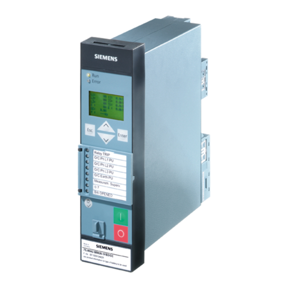
SIPROTEC 7SK80
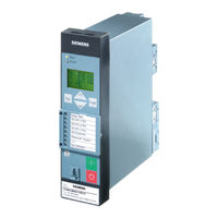
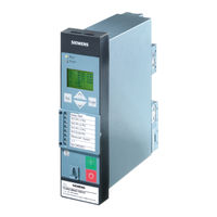
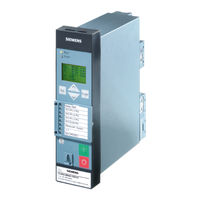
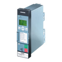
User Manuals: Siemens SIPROTEC 7SK80 Motor Protection
Manuals and User Guides for Siemens SIPROTEC 7SK80 Motor Protection. We have
6
Siemens SIPROTEC 7SK80 Motor Protection manuals available for free PDF download: Manual, Product Information
Siemens SIPROTEC 7SK80 Manual (512 pages)
SIPROTEC Motor Protection
Brand:
Siemens
| Category:
Engine
| Size: 21.49 MB
Table of Contents
Functions
3
Technical Data
4
Table of Contents
9
1 Introduction
17
Overall Operation
18
Application Scope
21
Characteristics
23
2 Functions
29
General
30
Functional Scope
30
Description
30
Setting Notes
30
Settings
32
Device, General Settings
34
Description
34
Setting Notes
35
Settings
36
Information List
37
Power System Data 1
39
Description
39
Setting Notes
39
Settings
49
Information List
52
Oscillographic Fault Records
52
Description
52
Setting Notes
53
Settings
54
Information List
54
Settings Groups
54
Description
54
Setting Notes
55
Settings
55
Information List
55
Power System Data 2
56
Description
56
Setting Notes
56
Settings
57
Information List
57
EN100-Module
58
Description
58
Setting Notes
58
Information List
58
Overcurrent Protection 50, 51, 50N, 51N
59
General
59
Definite Time High-Set Elements 50-3, 50-2, 50N-3, 50N-2
60
Definite Time Overcurrent Elements 50-1, 50N-1
63
Inverse Time Overcurrent Elements 51, 51N
66
Inverse Time Overcurrent Protection 51V (Voltage-Controlled / Voltage-Restraint)
69
Dynamic Cold Load Pickup Function
72
Inrush Restraint
72
Pickup Logic and Tripping Logic
75
Two-Phase Overcurrent Protection (Only Non-Directional)
76
Fast Busbar Protection Using Reverse Interlocking
76
Setting Notes
77
Settings
82
Information List
85
Directional Overcurrent Protection Ground 67, 67N
87
General
87
Directional Definite Time High-Current Elements 67N-2, 67N-3
88
Definite Time, Directional Overcurrent Element 67N-1
90
Inverse Time, Directional Overcurrent Element 67N-TOC
92
Interaction with Fuse Failure Monitor (FFM)
93
Dynamic Cold Load Pickup
94
Inrush Restraint
94
Determination of Direction
94
Setting Notes
96
Settings
100
Information List
102
Dynamic Cold Load Pickup
103
Description
103
Setting Notes
106
Settings
107
Information List
108
Voltage Protection 27, 59
109
Measurement Principle
109
Overvoltage Protection 59
111
Undervoltage Protection 27
112
Setting Notes
115
Settings
118
Information List
119
Negative Sequence Protection 46
120
Definite Time Characteristic
120
Inverse Time Characteristic 46-TOC
121
Setting Notes
124
Settings
127
Information List
127
Motor Protection (Motor Starting Protection 48, Motor Restart Inhibit 66, Load Jam Protection)
128
Motor Starting Protection 48
128
Description
128
Setting Notes
131
Motor Restart Inhibit 66
133
Description
133
Setting Notes
139
Load Jam Protection
143
Mode of Operation
143
Setting Notes
145
Motor (Motor Starting Protection 48, Motor Restart Inhibit 66, Load Jam Protection)
148
Settings
148
Information List
149
Frequency Protection 81 O/U
150
Description
150
Setting Notes
151
Settings
152
Information List
153
Thermal Overload Protection 49
154
Description
154
Setting Notes
158
Settings
162
Information List
163
Monitoring Functions
164
Measurement Supervision
164
General
164
Hardware Monitoring
164
Software Monitoring
167
Monitoring of the Transformer Circuits
167
Measuring Voltage Failure Detection
169
Broken Wire Monitoring of Voltage Transformer Circuits
173
Setting Notes
175
Settings
176
Information List
177
Trip Circuit Supervision 74TC
178
Description
178
Setting Notes
181
Settings
182
Information List
182
Malfunction Responses of the Monitoring Functions
182
Description
182
Ground Fault Protection 64, 67N(S), 50N(S), 51N(S)
185
Ground Fault Detection for Cos-Φ- / Sin-Φ Measurement (Standard Method)
185
Ground Fault Detection for V0/I0-Φ Measurement
192
Ground Fault Location
196
Setting Notes
197
Settings
204
Information List
206
Intermittent Ground Fault Protection
207
Description
207
Setting Notes
211
Settings
212
Information List
212
Dir. Intermittent Earth Fault Protection
213
Description
213
Setting Notes
216
Settings
217
Information List
217
Breaker Failure Protection 50BF
218
Description
218
Setting Notes
222
Settings
223
Information List
223
Flexible Protection Functions
224
Description
224
Setting Notes
229
Settings
234
Information List
236
Reverse-Power Protection Application with Flexible Protection Function
237
Description
237
Implementation of the Reverse Power Protection
240
Configuring the Reverse Power Protection in DIGSI
242
Temperature Detection Via RTD Box
245
Description
245
Setting Notes
247
Settings
250
Information List
255
Phase Rotation
256
Description
256
Setting Notes
257
Function Logic
258
Pickup Logic of the Entire Device
258
Tripping Logic of the Entire Device
259
Setting Notes
259
Auxiliary Functions
260
Message Processing
260
Leds and Binary Outputs (Output Relays)
260
Information Via Display Field or PC
261
Information to a Control Center
262
Statistics
263
Description
263
Circuit Breaker Maintenance
263
Motor Statistics
269
Setting Notes
270
Information List
272
Measurement
273
Display of Measured Values
273
Transmitting Measured Values
275
Information List
276
Average Measurements
277
Description
277
Setting Notes
277
Settings
278
Information List
278
Min/Max Measurement Setup
278
Description
278
Setting Notes
279
Settings
279
Information List
279
Set Points for Measured Values
281
Setting Notes
281
Set Points for Statistic
282
Description
282
Setting Notes
282
Information List
282
Energy Metering
283
Description
283
Setting Notes
283
Settings
283
Information List
283
Commissioning Aids
284
Description
284
Command Processing
286
Control Device
286
Description
286
Information List
287
Command Types
288
Description
288
Command Sequence
289
Description
289
Interlocking
290
Description
290
Command Logging
297
Description
297
Notes on Device Operation
298
Different Operation
298
3 Mounting and Commissioning
301
Mounting and Connections
302
Configuration Information
302
Hardware Modifications
306
Disassembly
306
Connections of the Current Terminals
309
Connections of the Voltage Terminals
310
Connection of the Temperature Sensors to the Extension Module I/O 2
311
Interface Modules
313
Reassembly
316
Installation
317
General
317
Panel Flush Mounting
318
Cubicle Mounting
319
Panel Surface Mounting
320
Checking Connections
321
Checking the Data Connections of the Interfaces
321
Checking the System Connections
325
Commissioning
327
Test Mode and Transmission Block
328
Testing the System Interface (at Port B)
328
Configuring Communication Modules
330
Checking the Status of Binary Inputs and Outputs
333
Tests for Breaker Failure Protection
335
Testing User-Defined Functions
337
Current, Voltage, and Phase Rotation Testing
337
Testing the Reverse Interlocking Scheme
339
Direction Check with Load Current
340
Polarity Check for Voltage Input V
341
Ground Fault Check
341
Polarity Check for Current Input I
342
Checking the Temperature Detection
344
Trip/Close Tests for the Configured Operating Devices
346
Creating Oscillographic Recordings for Tests
346
Final Preparation of the Device
348
4 Technical Data
349
General Device Data
350
Analog Inputs
350
Auxiliary Voltage
351
Binary Inputs and Outputs
351
Communication Interfaces
352
Electrical Tests
355
Mechanical Tests
356
Climatic Stress Tests
357
Service Conditions
358
Constructive Design
358
UL Certification Conditions
359
Definite-Time Overcurrent Protection
360
Inverse-Time Overcurrent Protection
362
Directional Overcurrent Protection Ground
373
Inrush Restraint
374
Dynamic Cold Load Pickup
375
Voltage Protection
376
Negative Sequence Protection (Definite-Time Characteristic)
378
Negative Sequence Protection (Inverse-Time Characteristics)
379
Motor Starting Time Supervision
385
Motor Restart Inhibit
386
Load Jam Protection
387
Frequency Protection
388
Thermal Overload Protection
389
Ground Fault Detection (Sensitive/Insensitive)
391
Intermittent Ground Fault Protection
395
Directional Intermittent Ground Fault Protection
396
Breaker Failure Protection 50BF
397
Flexible Protection Functions
398
Temperature Detection
401
User-Defined Functions (CFC)
403
Additional Functions
408
Switching Device Control
413
Dimensions
414
Panel Flush and Cubicle Mounting (Housing Size 1/6)
414
Panel Surface Mounting (Housing Size 1/6)
415
Bottom View
416
Appendix
417
Ordering Information and Accessories
418
Ordering Information
418
7Sk80 V4.7
418
Accessories
421
A.1.2 Accessories
421
Terminal Assignments
423
7SK80 - Housing for Panel Flush Mounting and Cubicle Installation and for Panel Surface Mounting
423
A.2 Terminal Assignments
423
Connection Examples
429
A.3 Connection Examples
429
Connection Example for RTD Box
440
Connection Examples for SICAM I/O Units and RTD Box
440
Current Transformer Requirements
442
Accuracy Limiting Factors
442
Effective and Rated Accuracy Limiting Factor
442
Calculation Example According to IEC 60044-1
442
Class Conversion
443
Cable Core Balance Current Transformer
443
General
443
Requirements
443
A.4.2 Class Conversion
443
Class Accuracy
444
Default Settings
445
Leds
445
A.5 Default Settings
445
Binary Input
446
Binary Output
447
Function Keys
447
A.5.3 Binary Output
447
Default Display
448
A.5.5 Default Display
448
Protocol-Dependent Functions
451
Functional Scope
452
A.7 Functional Scope
452
Settings
454
A.8 Settings
454
Information List
471
A.9 Information List
471
Group Alarms
490
A.10 Group Alarms
490
Measured Values
491
A.11 Measured Values
491
Literature
495
Glossary
497
Index
509
Advertisement
Siemens SIPROTEC 7SK80 Manual (490 pages)
Motor Protection
Brand:
Siemens
| Category:
Protection Device
| Size: 12.65 MB
Table of Contents
Functions
3
Table of Contents
9
1 Introduction
17
Overall Operation
18
Application Scope
21
Characteristics
23
2 Functions
27
General
28
Functional Scope
28
Description
28
Setting Notes
28
Settings
30
Device, General Settings
32
Description
32
Setting Notes
32
Settings
33
Information List
33
Power System Data 1
34
Description
34
Setting Notes
34
Settings
45
Information List
47
Oscillographic Fault Records
48
Description
48
Setting Notes
49
Settings
49
Information List
49
Settings Groups
50
Description
50
Setting Notes
50
Settings
50
Information List
51
Power System Data 2
51
Description
51
Setting Notes
51
Settings
52
Information List
52
EN100-Module
53
Functional Description
53
Information List
53
Overcurrent Protection 50, 51, 50N, 51N
54
General
54
Definite Time High-Set Elements 50-3, 50-2, 50N-3, 50N-2
55
Definite Time Overcurrent Elements 50-1, 50N-1
58
Inverse Time Overcurrent Elements 51, 51N
61
Dynamic Cold Load Pickup Function
64
Inrush Restraint
64
Pickup Logic and Tripping Logic
67
Two-Phase Overcurrent Protection (Only Non-Directional)
68
Fast Busbar Protection Using Reverse Interlocking
68
Setting Notes
69
Settings
74
Information List
77
Directional Ground Overcurrent Protection 67N
79
General
79
Definite Time, Directional High-Set Current Element 67N-2
80
Definite Time, Directional Overcurrent Element 67N-1
81
Inverse Time, Directional Overcurrent Element 67N-TOC
83
Interaction with Fuse Failure Monitor (FFM)
85
Dynamic Cold Load Pickup
85
Inrush Restraint
85
Determination of Direction
86
Setting Notes
88
Settings
92
Information List
93
Dynamic Cold Load Pickup
94
Description
94
Setting Notes
97
Settings
98
Information List
99
Voltage Protection 27, 59
100
Measurement Principle
100
Overvoltage Protection 59
102
Undervoltage Protection 27
103
Setting Notes
106
Settings
109
Information List
110
Negative Sequence Protection 46
111
Definite Time Characteristic
111
Setting Notes
115
Settings
118
Information List
118
Motor Protection (Motor Starting Protection 48, Motor Restart Inhibit 66, Load Jam Protection)
119
Motor Starting Protection 48
119
Description
119
Setting Notes
122
Motor Restart Inhibit 66
125
Description
125
Setting Notes
131
Load Jam Protection
135
Mode of Operation
135
Setting Notes
137
Motor (Motor Starting Protection 48, Motor Restart Inhibit 66, Load Jam Protection)
139
Settings
139
Information List
141
Frequency Protection 81 O/U
142
Description
142
Setting Notes
143
Settings
144
Information List
145
Thermal Overload Protection 49
146
Description
146
Setting Notes
150
Settings
155
Information List
155
Monitoring Functions
156
Measurement Supervision
156
General
156
Hardware Monitoring
156
Software Monitoring
159
Monitoring of the Transformer Circuits
159
Measuring Voltage Failure Detection
161
Broken Wire Monitoring of Voltage Transformer Circuits
166
Setting Notes
167
Settings
169
Information List
170
Trip Circuit Supervision 74TC
170
Description
171
Setting Notes
173
Settings
174
Information List
174
Malfunction Responses of the Monitoring Functions
174
Description
174
Ground Fault Protection 64, 67N(S), 50N(S), 51N(S)
177
Ground Fault Detection for Cos-Φ- / Sin-Φ Measurement (Standard Method)
177
Ground Fault Detection for V0/I0-Φ Measurement
184
Ground Fault Location
189
Setting Notes
190
Settings
196
Breaker Failure Protection 50BF
199
Description
199
Setting Notes
203
Settings
204
Information List
204
Flexible Protection Functions
205
Description
205
Setting Notes
210
Settings
215
Information List
217
Reverse-Power Protection Application with Flexible Protection Function
218
Description
218
Implementation of the Reverse Power Protection
221
Configuring the Reverse Power Protection in DIGSI
223
Temperature Detection Via RTD Boxes
226
Description
226
Setting Notes
228
Settings
231
Information List
236
Phase Rotation
237
Description
237
Setting Notes
238
Function Logic
239
Pickup Logic of the Entire Device
239
Tripping Logic of the Entire Device
240
Setting Notes
240
Auxiliary Functions
241
Message Processing
241
Leds and Binary Outputs (Output Relays)
241
Information Via Display Field or PC
242
Information to a Control Center
243
Statistics
244
Description
244
Circuit Breaker Maintenance
245
Motor Statistics
251
Setting Notes
251
Information List
254
Measurement
255
Display of Measured Values
256
Transmitting Measured Values
258
Information List
258
Average Measurements
260
Description
260
Setting Notes
260
Settings
260
Information List
261
Min/Max Measurement Setup
261
Description
261
Setting Notes
261
Settings
262
Information List
262
Set Points for Measured Values
264
Setting Notes
264
Set Points for Statistic
265
Description
265
Setting Notes
265
Information List
265
Energy Metering
266
Description
266
Setting Notes
266
Settings
266
Information List
266
Commissioning Aids
267
Description
267
Breaker Control
269
Control Device
269
Description
269
Information List
270
Command Types
271
Description
271
Command Sequence
272
Description
272
Interlocking
273
Description
273
Command Logging
280
Description
280
Notes on Device Operation
281
Different Operation
281
3 Mounting and Commissioning
285
Mounting and Connections
286
Configuration Information
286
Hardware Modifications
290
Disassembly
290
Connections of the Current Terminals
293
Connections of the Voltage Terminals
295
Connection of the Temperature Sensors to the I/O 2 Extension Module
295
Interface Modules
298
Reassembly
300
Installation
302
General
302
Panel Flush Mounting
303
Cubicle Mounting
304
Panel Surface Mounting
305
Checking Connections
306
Checking the Data Connections of the Interfaces
306
Checking the System Connections
310
Commissioning
312
Test Mode and Transmission Block
313
Testing the System Interface (at Port B)
313
Configuring Communication Modules
315
Checking the Status of Binary Inputs and Outputs
318
Tests for Circuit Breaker Failure Protection
321
Testing User-Defined Functions
322
Current, Voltage, and Phase Rotation Testing
323
Testing the Reverse Interlocking Scheme
324
Direction Check with Load Current
325
Polarity Check for Voltage Input V
326
Ground Fault Check
326
Polarity Check for Current Input I
327
Checking the Temperature Detection
329
Trip/Close Tests for the Configured Operating Devices
330
Creating Oscillographic Recordings for Tests
331
Final Preparation of the Device
332
4 Technical Data
334
General Device Data
334
Analog Inputs
334
Auxiliary Voltage
335
Binary Inputs and Outputs
336
Communication Interfaces
337
Electrical Tests
339
Mechanical Stress Tests
342
Climatic Stress Tests
343
Service Conditions
343
Design
344
UL-Certification Conditions
344
Definite-Time Overcurrent Protection 50(N)
345
Inverse-Time Overcurrent Protection 51(N)
347
Directional Ground Overcurrent Protection 67N
358
Inrush Restraint
359
Dynamic Cold Load Pickup
360
Voltage Protection
361
Negative Sequence Protection
363
Negative Sequence Protection 46-TOC
364
Motor Starting Protection
370
Motor Restart Inhibit
371
Load Jam Protection
372
Frequency Protection 81 O/U
373
Thermal Overload Protection
374
Ground Fault Protection 64, 67N(S), 50N(S), 51N(S)
376
Breaker Failure Protection 50BF
379
Flexible Protection Functions
380
Temperature Detection
383
User-Defined Functions (CFC)
385
Additional Functions
390
Breaker Control
395
Dimensions
396
Panel Flush and Cubicle Mounting (Housing Size 1/6)
396
Panel Surface Mounting (Housing Size 1/6)
397
Bottom View
398
Appendix
399
Ordering Information and Accessories
400
Ordering Information
400
7Sk80 V4.6
400
Accessories
403
A.1.2 Accessories
403
Terminal Assignments
405
7SK80 - Housing for Panel Flush Mounting and Cubicle Installation and for Panel Surface Mounting
405
A.2 Terminal Assignments
405
Connection Examples
411
A.3 Connection Examples
411
Connection Examples for RTD Box
422
Current Transformer Requirements
424
Accuracy Limiting Factors
424
Effective and Rated Accuracy Limiting Factor
424
Calculation Example According to IEC 60044-1
424
Class Conversion
425
A.4.2 Class Conversion
425
Cable Core Balance Current Transformer
426
General
426
Requirements
426
Class Accuracy
426
Default Settings
427
Leds
427
A.5 Default Settings
427
Binary Input
428
A.5.2 Binary Input
428
Binary Output
429
Function Keys
429
A.5.3 Binary Output
429
Default Display
430
A.5.5 Default Display
430
Protocol-Dependent Functions
433
Functional Scope
434
A.7 Functional Scope
434
Settings
436
A.8 Settings
436
Information List
451
A.9 Information List
451
Group Alarms
468
A.10 Group Alarms
468
Measured Values
469
A.11 Measured Values
469
Literature
473
Glossary
475
Index
487
Siemens SIPROTEC 7SK80 Product Information (80 pages)
Brand:
Siemens
| Category:
Control Unit
| Size: 2.91 MB
Table of Contents
English
3
Table of Contents
3
General
4
Notes on Safety
5
Statement of Conformity
7
Unpacking and Re-Packing
8
Storage and Transport
9
Dimensions
10
Installation Notes
13
Connection Notes
14
Limit Values of Inputs and Outputs
26
General Diagrams
29
Operating Pre-Conditions
39
Deutsch
43
Allgemeines
44
Hinweise zu Ihrer Sicherheit
45
Angaben zur Konformität
47
Aus- und Einpacken des Gerätes
48
Lagerung und Transport
49
Maßbilder
50
Montagehinweise
53
Hinweise für den Anschluss
54
Grenzdaten der Ein- und Ausgänge
66
Übersichtspläne
69
Bedienvoraussetzungen
79
Advertisement
Siemens SIPROTEC 7SK80 Manual (43 pages)
Overcurrent Protection, Motor Protection, Voltage and Frequency Protection
Brand:
Siemens
| Category:
Relays
| Size: 0.48 MB
Table of Contents
Instructions and Warnings
5
Table of Contents
7
Table of Contents
8
Notes to SIPROTEC Objects
9
Binary Inputs / Annunciations
10
Error with a Summary Alarm
10
Alarm Summary Event
10
Binary Outputs / Commands
11
Stop Data Transmission
11
Single Commands
11
Control Mode REMOTE
11
Analog Inputs / Measured Values
12
Changing the Setting Group
12
Scaling
13
Metered Measurands
13
DNP V3.0 Device Profile
15
Implementation Table
16
Device Profile Document
18
Sends/Executes Control Operations
19
Timesync Information
19
Sends Unsolicited Responses
20
Default Counter Object/Variation
20
Sends Static Data in Unsolicited Responses
20
Point Lists
21
Functional Scope
22
7SJ80 Functional Scope
22
7SK80 Functional Scope
23
7RW80 Functional Scope
24
Binary Input Points
25
Auto-Reclose Function
25
Overcurrent Protection
25
Inrush Function
25
Directional Overcurrent Protection
25
Negative Sequence Protection
26
Over/Underfrequency Protection
26
Under/Overvoltage Protection
26
Sensitive) Ground Fault Protection
26
Startup Counter for Motor
27
Startup Supervision of Motors
27
Trip Circuit Supervision
27
Internal Mode Status
27
Control Switches Return Position Indication(Double Point Commands)
27
Internal Controls
28
Output Channels Return Position Indication (Single Point Commands)
28
Internal Controls
29
Control Relay Output Blocks/Binary Output Status
31
External Commands (Double Point Commands)
31
Binary Output Status Points
32
Internal Commands
32
Output Channel (User Defined Single Point Output Commands)
32
Counters
34
Analog Inputs
35
Recorded Measured Values
35
Min/Max Values
35
Statistic Values
36
Glossary
39
Index
41
Siemens SIPROTEC 7SK80 Manual (62 pages)
Modbus TCP Profile
Brand:
Siemens
| Category:
Protection Device
| Size: 2.24 MB
Table of Contents
Preface
3
Table of Contents
7
1 Characteristic of the Modbustcp Module
9
General
10
Identification of Module and Firmware
12
Supported Modbus Functions and Register Types
14
Time Synchronization
15
Table of Parameters
16
Further Ethernet Services and Protocols
17
Services
17
Modbus TCP with IEC 61850 and GOOSE
17
2 Configuration in DIGSI 4
19
Inserting and Adjusting a New Project
20
Setting the Interfaces
27
Customization of the Allocations
30
3 Scaling of Measured Values
41
Measurement Conversion
42
Number Representation Depending on the Parameterization
43
Counter-Value Scaling
44
4 Time Synchronization
45
General
46
Time Synchronization with Modbus TCP
47
Time/Date Transfer from Modbus TCP Master
49
5 Modbus TCP Diagnosis for EN100+ Module
51
HTML Page
52
Modbus TCP Error Indication
54
6 Redundant Modbus TCP
55
General Introduction and Requirements
56
Configuration in DIGSI 4
57
7 Technical Data
59
Technical Data of EN100
60
Index
61
Siemens SIPROTEC 7SK80 Manual (42 pages)
Overcurrent Protection; Motor Protection; Voltage and Frequency Protection;
Brand:
Siemens
| Category:
Relays
| Size: 0.4 MB
Table of Contents
Preface
3
Revision Index
7
Table of Contents
9
Modbus Register Map Organization
11
Explanations
12
Functional Scope
14
Coil Status Registers (0X Register)
17
Registers 00001 to 00018: Double Commands
17
Registers 00019 to 00043: Single Commands and Taggings
18
Registers 00044 to 00048: Internal Commands
19
Registers 00257 to 00264: Exception Flags
21
Input Status Registers (1X Register)
22
Registers 10001 to 10024: User-Defined Annunciations
22
Registers 10025 to 10033: Auto-Reclose Function
23
Registers 10034 to 10045: Overcurrent Protection
23
Registers 10046 to 10053: Directional Overcurrent Protection
24
Registers 10054 to 10058: Negative Sequence Protection
24
Registers 10059 to 10063: Frequency Protection
24
Registers 10064 to 10069: Under/Overvoltage Protection
25
Registers 10070 to 10081: (Sensitive) Ground Fault Protection
25
Registers 10082 to 10083: Startup Counter for Motors
25
1.4.10 Registers 10084 to 10086: Startup Supervision of Motors
26
1.4.11 Registers 10087 to 10088: Trip Circuit Supervision
26
1.4.12 Registers 10089 to 10090: Local/Mode
26
Input Registers (3X Register)
27
Holding Registers (4X Register)
29
Registers 40001 to 40036: System Information
29
Registers 40065 to 40069: Time Synchronization
30
Register 40129: Diagnostics
31
Registers 40201 to 40208: Metered Measurands
32
Registers 40301 to 40324: Statistic Values
33
Registers 40351 to 40520: Min/Max Values of Measured Values
34
Registers 40601 to 40626: Event Recorder ("Sequence of Events")
37
Advertisement
Related Products
Siemens SIMOTICS SD SH 71 315 Series
Siemens SIPROTEC 7SK81
Siemens 7 SK 88 A Series
Siemens 7SJ511
Siemens 7SA513BB Series
Siemens 7SG164 Ohmega 400 Series
Siemens 7SG23 MSCDN - MP2A
Siemens 7SD502
Siemens Reyrolle 7SR46
Siemens 7SR1002 Argus
Siemens Categories
Industrial Equipment
Controller
Control Unit
Oven
Washer
More Siemens Manuals
Login
Sign In
OR
Sign in with Facebook
Sign in with Google
Upload manual
Upload from disk
Upload from URL