Sign In
Upload
Manuals
Brands
Siemens Manuals
Transmitter
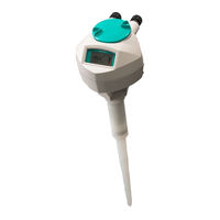
SITRANS LR200 7ML5423
Siemens SITRANS LR200 7ML5423 Manuals
Manuals and User Guides for Siemens SITRANS LR200 7ML5423. We have
1
Siemens SITRANS LR200 7ML5423 manual available for free PDF download: Operating Instructions Manual
Siemens SITRANS LR200 7ML5423 Operating Instructions Manual (212 pages)
Radar Transmitter With mA/HART
Brand:
Siemens
| Category:
Transmitter
| Size: 3.99 MB
Table of Contents
Table of Contents
3
Introduction
10
Purpose of this Documentation
10
Checking the Consignment
10
Security Information
10
Transportation and Storage
11
Notes on Warranty
11
Safety Notes
12
Preconditions for Safe Use
12
Laws and Directives
12
FCC Conformity
13
CE Electromagnetic Compatibility (EMC) Conformity
13
Radio Equipment Directive (RED) Compliance (Europe)
14
Conformity with European Directives
14
Requirements for Special Applications
15
Use in Hazardous Areas
15
Qualified Personnel for Hazardous Area Applications
15
Lithium Batteries
16
Description
17
SITRANS LR200 Overview
17
Programming
18
Applications
18
Approvals and Certificates
18
Process Connections
18
Installing/Mounting
19
Basic Safety Notes
19
Mounting
21
Mounting Location
21
Nozzle Design
22
Nozzle Location
23
Access for Programming
24
Orientation in a Vessel with Obstructions
25
Installation
27
Installation Instructions
27
Disassembly
28
Connecting
29
Basic Safety Notes
29
Connecting SITRANS LR200
30
Connecting HART
32
Typical PLC Configuration with HART
32
Nameplates for Hazardous Area Installations
33
Intrinsically Safe Wiring
33
Device Nameplate (ATEX/IECEX/INMETRO/RCM)
33
Device Nameplate (FM/CSA)
34
Instructions Specific to Hazardous Area Installations
34
Reference European ATEX Directive 2014/34/EU, Annex II, 1.0.6)
34
Operating
36
Basic Safety Notes
36
Local Operation
36
Operating Via the Handheld Programmer
36
Activating SITRANS LR200
37
Quick Start Wizard Via the Handheld Programmer
43
Auto False Echo Suppression
45
Requesting an Echo Profile
46
Application Examples
47
Level Application Example
47
Horizontal Vessel with Volume Measurement
49
Sliding Waveguide on Anaerobic Digesters
51
Application with Stillpipe
52
Propagation Factor/Stillpipe Diameter
53
Remote Operation
54
Operating Via SIMATIC PDM
54
Functions in SIMATIC PDM
54
Initial Setup
55
Quick Start Wizard Via SIMATIC PDM
56
Changing Parameter Settings Using SIMATIC PDM
63
Parameters Accessed Via Pull-Down Menus
64
Operating Via AMS Device Manager
76
Functions in AMS Device Manager
76
Maintenance and Diagnostics
88
Communication
89
Security
89
Device Diagnostics
90
Password Protection
91
User Manager Utility
91
AMS Device Menu
92
Operating Via FDT (Field Device Tool)
95
Device Type Manager (DTM)
95
Sitrans Dtm
96
The Instrument EDD
96
Configuring a New Device Via FDT
96
Parameter Reference
97
Quick Start (1.)
98
Setup (2.)
98
Sensor (2.2.)
99
Units (2.2.1.)
99
Sensor Mode (2.2.2.)
99
Material (2.2.3.)
99
Damping Filter (2.2.4.)
100
Antenna (2.2.5.)
100
Calibration (2.3.)
100
Low Calibration Point (2.3.1.)
100
High Calibration Point (2.3.2.)
101
Sensor Offset (2.3.3.)
101
Rate (2.4.)
101
Response Rate (2.4.1.)
101
Fill Rate/Min (2.4.2.)
102
Empty Rate/Min (2.4.3.)
102
Fail-Safe (2.5.)
103
Material Level (2.5.1.)
103
Timer (2.5.2.)
103
Level (2.5.3.)
104
Analog Output Scaling (2.6.)
104
Current Output Function (2.6.1.)
104
Start of Scale (4 Ma Setpoint) (2.6.2.)
105
Full Scale (20 Ma Setpoint) (2.6.3.)
105
Control Range; Lower Limit (Min Ma Limit) (2.6.4.)
106
Control Range; Upper Limit (Max Ma Limit) (2.6.5.)
106
Ma Output Value (2.6.6.)
106
Linearization (2.7.)
106
Volume (2.7.1.)
106
Vessel Shapes (2.7.1.1.)
107
Maximum Volume (2.7.1.2.)
108
Dimension a (2.7.1.3.)
108
Dimension L (2.7.1.4.)
109
Signal Processing (2.8.)
110
Near Range (2.8.1.)
110
Far Range (2.8.2.)
111
Propagation Factor (2.8.3.)
111
Echo Select (2.8.4.)
111
Sampling (2.8.5.)
113
Echo Quality (2.8.6.)
114
TVT Setup (2.8.7.)
115
TVT Shaper (2.8.8.)
117
Measured Values (2.8.9.)
119
Diagnostics (3.)
119
Echo Profile (3.1.)
119
Electronics Temperature (3.2.)
120
Current Internal Temperature (3.2.1.)
120
Highest Value (3.2.2.)
120
Lowest Value (3.2.3.)
120
Service (4.)
120
Master Reset (4.1.)
120
Remaining Device Lifetime (4.2.)
121
Lifetime Expected (4.2.1.)
122
Time in Operation (4.2.2.)
122
Remaining Lifetime (4.2.3.)
122
Reminder Activation (4.2.4.)
122
Reminder 1 (Required) (4.2.5.)
123
Reminder 2 (Demanded) (4.2.6.)
123
Maintenance Status (4.2.7.)
123
Acknowledge Status (4.2.8.)
123
Acknowledge (4.2.9.)
123
Remaining Sensor Lifetime (4.3.)
124
Lifetime Expected (4.3.1.)
124
Time in Operation (4.3.2.)
124
Remaining Lifetime (4.3.3.)
125
Reminder Activation (4.3.4.)
125
Reminder 1 (Required) (4.3.5.)
125
Reminder 2 (Demanded) (4.3.6.)
125
Maintenance Status (4.3.7.)
125
Acknowledge Status (4.3.8.)
125
Acknowledge (4.3.9.)
126
Service Schedule (4.4.)
126
Service Interval (4.4.1.)
127
Time Since Last Service (4.4.2.)
127
Time until Next Service (4.4.3.)
127
Reminder Activation (4.4.4.)
127
Reminder 1 (Required) (4.4.5.)
128
Reminder 2 (Demanded) (4.4.6.)
128
Maintenance Status (4.4.7.)
128
Acknowledge Status (4.4.8.)
128
Acknowledge (4.4.9.)
128
Calibration Schedule (4.5.)
129
Calibration Interval (4.5.1.)
129
Time Since Last Calibration (4.5.2.)
130
Time until Next Calibration (4.5.3.)
130
Reminder Activation (4.5.4.)
130
Reminder 1 (Required) (4.5.5.)
130
Reminder 2 (Demanded) 4.5.6.)
131
Maintenance Status (4.5.7.)
131
Acknowledge Status (4.5.8.)
131
Acknowledge (4.5.9.)
131
Manufacture Date (4.6.)
131
Powered Hours (4.7.)
131
Power-On Resets (4.8.)
132
LCD Fast Mode (4.9.)
132
LCD Contrast (4.10.)
132
Memory Test (4.11)
133
Communication (5.)
133
Device Address (5.1.)
133
Security (6.)
134
Remote Access (6.1.)
134
Access Control (6.1.1.)
134
Local Access (6.2.)
134
Write Protect (6.2.1.)
134
Pin to Unlock (6.2.2.)
135
Language (7.)
135
Service and Maintenance
136
Maintenance and Repair
136
Maintenance
136
Cleaning
136
Return Procedure
137
Disposal
138
Replacing the Antenna
138
Diagnosing and Troubleshooting
139
Communication Troubleshooting
139
Device Status Icons
139
General Fault Codes
141
Operation Troubleshooting
144
Technical Data
146
Power
146
Performance
146
Interface
147
Construction
148
Operating Conditions
149
Process
149
Approvals Data
150
Programmer (Infrared Keypad)
151
Programmer Data - 7ML1930-1BK
151
Dimension Drawing
152
Uni-Construction Polypropylene Rod Antenna
152
Antenna Options
154
Threaded Connection, PFTE Rod
154
PTFE Rod Antenna, Flat-Face Flange
155
Threaded Connection, PTFE Rod, External Shield
156
Flat-Face Flange with Horn Antenna and Waveguide Extension
157
Flanged Horn Dimensions
158
Raised-Face or Flat-Face Flange with Waveguide
158
Raised-Face Flange Per en 1092-1
160
Raised-Face Flange Dimensions
161
Raised-Face Flange Markings
161
Flat-Face Flange (Constant Thickness Series)
162
Flat-Face Flange Dimensions
163
Flat-Face Markings
164
Threaded Connection Markings
164
Flange Mounting Instructions
165
Rod Assembly
166
Mounting Guidelines
167
Nozzle Fabrication
167
Nozzle Design
167
Horn Antennas
168
Threaded Rod Antenna
168
Sanitary Rod Antenna
169
Waveguide Antenna
169
Horn with Waveguide Extensions
170
Technical Reference
171
Principles of Operation
171
Echo Processing
171
Process Intelligence
171
Echo Selection
172
CLEF Range
175
Echo Threshold
175
Echo Lock
175
Auto False Echo Suppression
176
Measurement Range
177
Measurement Response
177
Damping
178
Analog Output
178
Sensor Mode
179
Loss of Echo (LOE)
179
Current Output Function
180
Fail-Safe Mode
180
Maximum Process Temperature Chart
181
Process Pressure/Temperature Derating Curves
182
Pressure Equipment Directive, PED, 2014/68/EU
183
PTFE Rod Antenna ASME Hole Pattern, 150 Lb
183
PTFE Rod Antenna, DN Hole Pattern, PN16
184
PFTE Rod Antenna Threaded Connection
185
Horn Antenna or Waveguide, ASME Hole Pattern, 150 Lb
186
Horn Antenna or Waveguide DN Hole Pattern, PN16
187
PFTE Rod Antenna, DN Hole Pattern, PN16, PN40
188
Horn Antenna or Waveguide, DN Hole Pattern, PN16, PN40
188
Startup Behaviour
189
Loop Power
189
Typical Connection Drawing
189
Allowable Operating Area of SITRANS LR200
190
Loop Voltage Versus Loop Resistance
190
HART Communication
192
Simatic Pdm
192
HART Electronic Device Description (EDD)
192
HART Communicator 375 Menu Structure
192
HART Version
195
Burst Mode
195
Certificates and Support
196
Technical Support
196
Certificates
196
QR Code Label
196
LCD Menu Structure
197
Abbreviations
201
Glossary
202
Index
208
Advertisement
Advertisement
Related Products
Siemens SITRANS LR200 7ML5422
Siemens SITRANS LR200 7ML5425
Siemens SITRANS LR25
Siemens SITRANS LR260
Siemens SITRANS LR560
Siemens SITRANS LR100
Siemens SITRANS LR110
Siemens SITRANS LR120
Siemens SITRANS LR150
Siemens SITRANS LR140
Siemens Categories
Industrial Equipment
Controller
Control Unit
Oven
Washer
More Siemens Manuals
Login
Sign In
OR
Sign in with Facebook
Sign in with Google
Upload manual
Upload from disk
Upload from URL