Sign In
Upload
Manuals
Brands
Siemens Manuals
Transmitter
SITRANS Series
Siemens SITRANS Series Manuals
Manuals and User Guides for Siemens SITRANS Series. We have
3
Siemens SITRANS Series manuals available for free PDF download: Operating Instructions Manual, Compact Operating Instructions
Siemens SITRANS Series Operating Instructions Manual (260 pages)
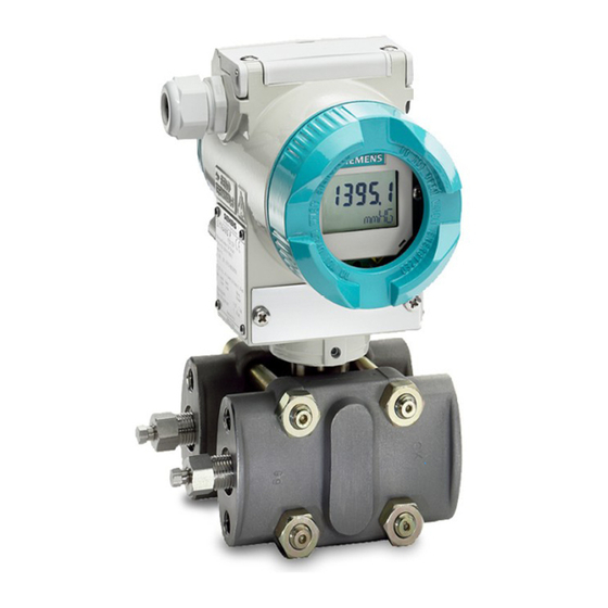
Pressure transmitter mA/HART
Brand:
Siemens
| Category:
Transmitter
| Size: 6.64 MB
Table of Contents
Table of Contents
3
1 Getting Started
11
Commissioning the Device with Display
11
Commissioning the Device Without Display
13
2 Introduction
15
Purpose of this Documentation
15
Document History
15
Product Compatibility
15
Scope of Validity of this Document
15
Checking the Consignment
16
Transportation and Storage
16
Notes on Warranty
17
3 Safety Information
19
Precondition for Use
19
Warning Symbols on the Device
19
Laws and Directives
19
Conformity with European Directives
20
Requirements for Special Applications
20
Use in Hazardous Areas
21
4 Description
23
Area of Application
23
Structure
25
Nameplate Layout
26
Functional Principle
28
Overview of Mode of Operation
28
How the Electronics Work
29
Measuring Cell Operation
30
Measuring Cell for Gauge Pressure
31
Measuring Cell for Gauge Pressure, Front-Flush Membrane
32
Measuring Cell for Absolute Pressure from the Gauge Pressure Series
32
Measuring Cell for Absolute Pressure, Front-Flush Membrane
33
Measuring Cell for Absolute Pressure from the Differential Pressure Series
34
Measuring Cell for Differential Pressure and Flow Rate
35
Measuring Cell for Level
36
Remote Seal
37
System Configuration
37
5 Installing/Mounting
39
Basic Safety Instructions
39
Installation Location Requirements
41
Devices with Marine Approval
42
Proper Mounting
42
Installation (Except Level)
43
Installation Configuration
43
Installation (Except Level)
44
Fastening with the Mounting Bracket
45
Installation (Level)
46
Mounting on the Container
47
Installing "Remote Seal
50
Remote Seal Installation
50
Installation of the Remote Seal with the Capillary Line
51
Removing
54
Rotating the Display
55
Rotating the Enclosure
57
6 Connecting
59
Basic Safety Instructions
59
Connecting the Device
62
Opening the Device
62
Connecting the Device
63
Closing the Device
64
Connect the Han Cable Socket to the Cable
65
Connect M12 Cable Socket to the Cable
66
7 Operating
69
Introduction
69
Operating the Device with Display
70
Display
70
Navigating in the Views
71
Measurement View
72
Display of Measured Values
73
Navigating in the Measurement View
74
Parameter View
74
List of Parameters on the Display
74
Navigating in the Parameter View
76
Edit View
76
Changing Parameter Values
77
Remote Operation
77
Requirements
77
Simatic Pdm
77
Locking the Device
78
Setting the Jumper
79
Enable User PIN
81
Enabling Button Lock
81
8 Commissioning
83
Basic Safety Instructions
83
Switching on the Supply Voltage
84
Commissioning the Device with Display
85
Commissioning the Device Without Display
87
Application Examples
88
Gauge Pressure, Absolute Pressure from the Differential Pressure Series and Absolute Pressure from the Gauge Pressure Series
88
Commissioning for Gases
88
Commissioning with Steam or Liquid
90
Differential Pressure and Volume Flow
91
Commissioning in Gaseous Environments
91
Commissioning with Liquids
92
Commissioning with Vapor
94
9 Parameter Assignment
97
Overview of Parameters and Functions
97
Parameter Assignment over Device with Display
101
Pressure Units [01]
101
Display of the Pressure Units
102
Setting the Pressure Units
103
Set Lower Range Value [02]/Set Upper Range Value [03]
104
Set Lower Range Value Parameter [02]
104
Set Upper Range Value Parameter [03]
104
Set Lower Range Value/Upper Range Value (Without Pressure Available)
104
Damping Value [04]
105
Set Damping Value
106
Application [05]
106
Pressure Measurement
108
Level Measurement
109
Volume and Mass Flow Measurements
111
Volume Measurement
114
Set Application
115
Application Point [06]
115
Zero Point Adjustment [07]
116
Adjusting Zero Point (Gauge Pressure)
116
Adjusting the Zero Point (Differential Pressure)
117
Adjusting Zero Point (Absolute Pressure)
117
Apply Lower Range Value [08]/Apply Upper Range Value [09]
118
Apply Lower Range Value Parameter [08]
118
Apply Upper Range Value Parameter [09]
118
Apply Lower Range Value/Upper Range Value (with Pressure Present)
119
Select Fault Current [10]
120
Lower Fault Current [11]
120
Upper Fault Current [12]
121
Lower Saturation Limit [13]
121
Upper Saturation Limit [14]
122
SV Selection [15]
123
Units [16]
123
Level Units [16]
123
Volume Units [16]
124
Volume Flow Units [16]
124
Mass Flow Units [16]
125
Temperature Units [17]
126
Lower Scaling Point [18]
126
Set Lower Scaling Point
127
Upper Scaling Point [19]
128
Set Upper Scaling Point
128
Low Flow Cut-Off [20]
128
Vessel Dimension a [21]
129
Vessel Dimension L [22]
129
Button Lock [23]
130
Enabling Button Lock
130
Disabling Button Lock
131
Change User PIN [24]
131
Recovery ID [25]
132
Display Recovery ID
132
PIN Recovery [26]
133
Recovering the User PIN
133
User PIN [27]
134
Enable User PIN
134
Disable User PIN
135
Active Device Mode [28]
136
Functional Safety [29]
136
Display Test [30]
136
Loop Test [31]
137
Loop Test with Preset Loop Current Value
137
Loop Test with User Defined Loop Current Value
138
Start View [32]
138
Pressure Reference [33]
139
Identify the Device [34]
139
Reset [35]
140
Reset to Sensor Calibration
140
Reset DAC Trim to the Factory Setting
140
Restore Ordered Configuration
141
Restore Factory Settings
141
Parameter Assignment over Remote Operation
142
Introduction
142
Quick Start
142
Identification
143
Simulation
143
Simulate Constant Pressure Values
144
Simulate Ramp Function
145
Simulate Diagnostics
145
Customized Characteristic Curve
146
Introduction
146
Custom Units" Parameter
147
Set Customized Characteristic Curve
147
Sensor Calibration
148
Diagnostics Functions
149
Limit Monitoring and Event Counter
149
Trend Log
152
10 Functional Safety
153
Safety Concept
153
Random and Systematic Errors
153
SIL-Compliant Product Version
153
Safety Function
154
Device Statuses
156
Safety Parameters
156
Operating Modes of the Device
157
Device Mode
157
Validation
158
Safety-Related Parameters
159
Device Mode "Functional Safety Enabled
159
Enabling Functional Safety
160
Enabling Functional Safety over Device with Display
160
Enabling Functional Safety over Remote Operation
163
Acknowledging Safety-Related Errors
168
Safety Critical Error" Device Mode
168
Acknowledging Safety-Related Errors Via Remote Operation
169
Disabling Functional Safety over Device with Display
170
Disabling Functional Safety over Remote Operation
171
Proof Test
172
Intervals and Rules for Proof Test
172
Documenting a Proof Test
173
Repair and Service
173
11 Service and Maintenance
175
Basic Safety Instructions
175
Cleaning
176
Cleaning the Enclosure
176
Servicing the Remote Seal Measuring System
176
Maintenance and Repair Work
177
Defining the Maintenance Interval
177
Checking the Gaskets
178
Check Cable Glands
179
Return Procedure
180
Disposal
180
12 Diagnostics and Troubleshooting
181
Device Status Symbols
181
Diagnostic Messages
184
Troubleshooting
190
Troubleshooting Functional Security
190
13 Technical Data
191
Input
191
Gauge Pressure
191
Gauge Pressure with Front-Flush Diaphragm
192
Gauge Pressure from the Differential Pressure Series
193
Absolute Pressure from the Gauge Pressure Series
194
Absolute Pressure with Front-Flush Diaphragm
195
Absolute Pressure from the Differential Pressure Series
196
Differential Pressure and Flow
197
Level
198
Measuring Accuracy of SITRANS P320
199
Reference Conditions
199
Effect of Auxiliary Power Supply
199
Gauge Pressure
199
Gauge Pressure from the Differential Pressure Series
201
Absolute Pressure from Gauge and Differential Pressure Series
202
Absolute Pressure with Front-Flush Diaphragm
203
Gauge Pressure with Front-Flush Diaphragm
204
Differential Pressure and Flow
205
Level
208
Measuring Accuracy of SITRANS P420
209
Reference Conditions
209
Effect of Auxiliary Power Supply
209
Gauge Pressure
209
Gauge Pressure from the Differential Pressure Series
210
Absolute Pressure from Gauge and Differential Pressure Series
212
Absolute Pressure with Front-Flush Diaphragm
213
Gauge Pressure with Front-Flush Diaphragm
214
Differential Pressure and Flow
214
Level
218
Output
219
Operating Conditions
219
Vibration Resistance
224
Construction
225
Torques
229
Display, Keyboard and Auxiliary Power
229
Certificates and Approvals
230
14 Dimension Drawings
233
SITRANS P320/P420 for Gauge Pressure and Absolute Pressure from the Gauge Pressure Series
233
SITRANS P320/P420 for Differential Pressure, Gauge Pressure, Flow and Absolute Pressure from the Differential Pressure Series
235
SITRANS P 320/P420 for Level
237
SITRANS P320/P420 (Front-Flush)
238
Note 3A and EHDG
239
Connections as Per en and ASME
239
F&B and Pharma Flange
240
PMC Style
244
Special Connections
245
Appendix
247
Technical Support
247
A.1 Technical Support
247
Certificates
248
QR Code Label
248
Checklist for Functional Safety
248
A.2 Certificates
248
List of Abbreviations
251
Pressure Transmitter Abbreviations
251
Glossary
253
Index
257
Advertisement
Siemens SITRANS Series Compact Operating Instructions (80 pages)
Brand:
Siemens
| Category:
Temperature Controller
| Size: 3.87 MB
Table of Contents
Table of Contents
3
1 Introduction
7
Purpose of this Documentation
7
Document History
7
Scope of Validity of this Document
7
Product Compatibility
8
Intended Use
8
Nameplate Layout
10
Nameplate Layout SITRANS TH
10
Nameplate Layout SITRANS TR
11
Nameplate Layout SITRANS TF
12
Checking the Consignment
12
Security Information
13
Transportation and Storage
13
Technical Specifications
13
Notes on Warranty
14
2 Safety Notes
15
Prerequisites for Safe Use
15
Warning Symbols on the Device
15
Laws and Directives
15
Conformity with European Directives
15
Requirements for Special Applications
16
Use in Hazardous Areas
16
3 Installing/Mounting
19
Basic Safety Notes
19
Atex/Iecex and Others
19
Safety Information for Installation in "Intrinsic Safety "Ia/Ib
19
Safety Information for Installation in "Non-Sparking Na/Ec" and "Intrinsic Safety IC
20
Csa/Fm
21
Safety Information for Installation in "Intrinsic Safety "Ia
21
Safety Information for Installation in "Non Incendive Na
22
Sitrans Tf
22
Unsuitable Cables, Cable Glands And/Or Plugs
22
Installing SITRANS TH in a Connection Head
23
Installing SITRANS TH on DIN Rail and G Rail
24
Installing SITRANS TR on DIN Rail
25
Mounting the SITRANS TF Single Chamber Housing
25
Mounting the SITRANS TF Dual Chamber Housing
26
Mounting Device to a Pole with Mounting Bracket
26
Mounting Device to the Wall with Mounting Bracket
27
Disassembly
29
4 Connecting
31
Basic Safety Notes
31
Connecting Device in Energized State in Hazardous Areas
32
Connecting TH320
33
Connecting TH420
34
Connecting TR320
35
Connecting TR420
37
Connecting the SITRANS TF Dual Chamber Housing
39
Opening the Device
39
Connecting the SITRANS TF320 Dual Chamber Housing
40
Connecting the SITRANS TF420 Dual Chamber Housing
42
Closing the Device
44
Connecting the SITRANS TF Single Chamber Housing
45
Opening the Device
45
Connecting the SITRANS TF320 Single Chamber Housing
46
Connecting the SITRANS TF420 Single Chamber Housing
48
Closing the Device
51
5 Commissioning
53
Basic Safety Notes
53
Commissioning the SITRANS TH/TR with 4
53
Commissioning SITRANS TH/TR with HART
54
Commissioning SITRANS TF with 4
55
Commissioning SITRANS TF with HART
56
Switching on the Supply Voltage
57
6 Service and Maintenance
59
Basic Safety Notes
59
Maintenance
59
Sitrans Tf
59
Cleaning
60
Maintenance and Repair Work
61
Sitrans Tf
61
Checking the Gaskets
62
Diagnostics Messages
62
Return Procedure
63
Disposal
63
7 Technical Specifications
65
Ambient Conditions
65
Construction
65
Common Specifications
66
Certificates and Approvals
67
Atex/Iecex and Related
67
Fm/Csa
72
Display
75
A Appendix A
77
Technical Support
77
Certificates
77
A.1 Technical Support
77
Index
79
Siemens SITRANS Series Compact Operating Instructions (60 pages)
Radar level transmitters with PROFIBUS PA
Brand:
Siemens
| Category:
Transmitter
| Size: 0.93 MB
Table of Contents
Table of Contents
3
1 Introduction
5
LR250 PA Manual Usage
5
Technical Publications
5
Purpose of this Documentation
5
Industrial Use Note
5
Checking the Consignment
6
Security Information
6
Transportation and Storage
7
Notes on Warranty
7
2 Safety Information
9
Preconditions for Safe Use
9
Safety Marking Symbols
9
Laws and Directives
9
FCC Conformity
10
Industry Canada Conformity
10
Industry Canada Conformity Note
11
Conformity with European Directives
11
Radio Equipment Directive (RED) 2014/53/EU
12
CE Electromagnetic Compatibility (EMC) Conformity
12
Improper Device Modifications
13
Requirements for Special Applications
13
Use in Hazardous Areas
13
3 Description
15
SITRANS LR250 Overview
15
4 Installing/Mounting
17
Basic Safety Information
17
Unsuitable Cables, Cable Glands And/Or Plugs
18
Pressure Applications
18
Pressure Equipment Directive, PED, 14/68/EU
19
Installation Location Requirements
19
Proper Mounting
20
Mounting Location
20
Nozzle Design
21
Nozzle Location
22
Installation Instructions
24
Threaded Versions
25
Flanged Versions
25
Hygienic Versions
27
Disassembly
28
5 Connecting
29
Basic Safety Information
29
Connecting SITRANS LR250
30
Wiring Setups for Hazardous Area Installations
32
Intrinsically Safe Wiring
33
Non-Sparking Wiring
34
Instructions Specific to Hazardous Area Installations
34
Reference European ATEX Directive 2014/34/EU)
34
6 Commissioning
37
Basic Safety Information
37
Programming SITRANS LR250
37
The LCD Display
37
Device Status Icons
39
Handheld Programmer (Part No. 7ML1930-1BK)
39
Programming Via the Handheld Programmer
41
Quick Start Wizard Via the Handheld Programmer
45
7 Remote Operation
49
SITRANS Communications: PROFIBUS PA
49
8 Service and Maintenance
51
Basic Safety Information
51
Cleaning
51
Maintenance and Repair Work
52
Unit Repair and Excluded Liability
53
Part Replacement
53
Disposal
54
Return Procedure
54
9 Technical Data
55
Power
56
Product Documentation and Support
57
Product Documentation
57
Technical Support
58
Index
59
Advertisement
Advertisement
Related Products
Siemens SITRANS TW
Siemens sitrans PROBE LU
Siemens SITRANS P series
Siemens SITRANS LR
Siemens SITRANS P ZD Series
Siemens SITRANS P DS III Series
Siemens SITRANS T Series
Siemens SITRANS Probe LR with mA/HART
Siemens SITRANS TH Series
Siemens SITRANS TF Series
Siemens Categories
Industrial Equipment
Controller
Control Unit
Oven
Washer
More Siemens Manuals
Login
Sign In
OR
Sign in with Facebook
Sign in with Google
Upload manual
Upload from disk
Upload from URL