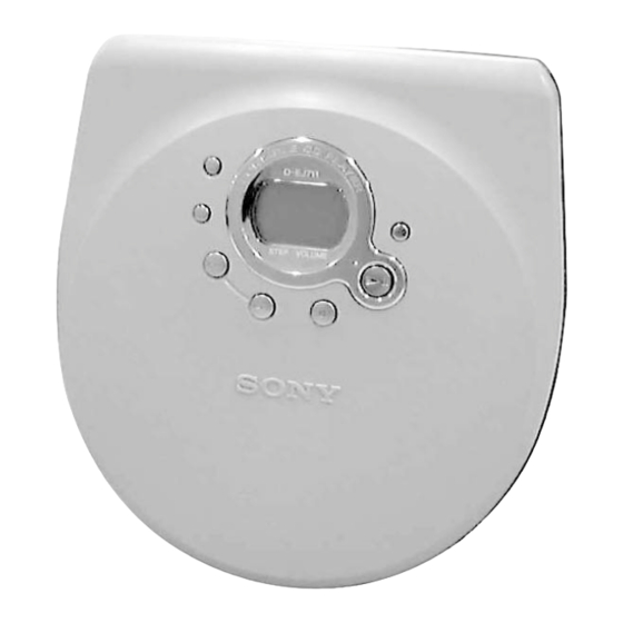
Sony D-E770 Service Manual
Portable cd player
Hide thumbs
Also See for D-E770:
- Operating instructions manual (28 pages) ,
- Manual de instrucciones (28 pages) ,
- Operating instructions manual (26 pages)
Table of Contents
Advertisement
Quick Links
D-E770/EJ711/EJ715
SERVICE MANUAL
Ver 1.1 2000. 05
•
Abbreviation
AUS : Australian model
CH
CND : Canadian model
EE
FR
MICROFILM
Photo : D-EJ711
SPECIFICATIONS
G
: German model
: Chinese model
HK
: Hong Kong model
JE
: Tourist model
: East European model
KR
: Korea model
: French model
Canadian Model
Australian Model
Chinese Model
Model Name Using Similar Mechanism
CD Mechanism Type
Optical Pick-up Name
PORTABLE CD PLAYER
US Model
D-EJ711/EJ715
AEP Model
UK Model
E Model
D-EJ715
Tourist Model
D-E770
NEW
CDM-3123EBA
DAX-23E
Advertisement
Table of Contents

Summary of Contents for Sony D-E770
- Page 1 D-E770/EJ711/EJ715 SERVICE MANUAL US Model D-EJ711/EJ715 Ver 1.1 2000. 05 Canadian Model AEP Model UK Model E Model Australian Model Chinese Model D-EJ715 Tourist Model Photo : D-EJ711 D-E770 Model Name Using Similar Mechanism CD Mechanism Type CDM-3123EBA Optical Pick-up Name...
-
Page 2: Table Of Contents
CRITIQUES POUR LA SÉCURITÉ DE FONCTIONNEMENT. NE COMPONENTS WITH SONY PARTS WHOSE PART NUMBERS REMPLACER CES COMPOSANTS QUE PAR DES PIÈSES SONY APPEAR AS SHOWN IN THIS MANUAL OR IN SUPPLEMENTS DONT LES NUMÉROS SONT DONNÉS DANS CE MANUEL OU PUBLISHED BY SONY. -
Page 3: Servicing Notes
SECTION 1 SERVICING NOTES Precautions for Checking Emission of Laser Diode NOTES ON HANDLING THE OPTICAL PICK-UP Laser light of the equipment is focused by the object lens in the BLOCK OR BASE UNIT optical pick-up so that the light focuses on the reflection surface of the disc. -
Page 4: General
SECTION 2 This section is extracted from instruction manual. GENERAL — 4 —... -
Page 5: Disassembly
SECTION 3 DISASSEMBLY Note : Follow the disassembly procedure in the numerical order given. 3-1. CABINET (UPPER) 1 Five screws (2 × 8) Three claws 3 Cabinet (upper) (There are 7 claws.) Claw 2 Open the lid, battery case. Three claws 3-2. -
Page 6: Electrical Adjustments
SECTION 4 ELECTRICAL ADJUSTMENTS The CD section adjustments are done automatically in this set. Focus bias Check In case of operation check, confirm that focus bias. Condition: • Hold the set in horizontal state. Precautions for Check 1. Perform check in the order given. Connection: oscilloscope 2. -
Page 7: Diagrams
SECTION 5 DIAGRAMS 5-1. IC PIN FUNCTION DESCRIPTION • IC801 TMP88CM22F (MICRO COMPUTER) Pin No. Pin Name Description — Digital GND — FOK_1 FOK input AGC PWM control (f=7.8kHz) AGCPWM_O XWRE monitor (for debug purpose on) XQOK monitor (for debug purpose on) AMUTE_O Analog mute on VCC2ON_O... - Page 8 Pin No. Pin Name Description — Charge pump C — Charge pump C — 0.5Vcpu input — Charge pump C — Charge pump C STOP STOP mode release signal input TEST 68k pull-down SCSY_0 External BB control XBACKLIGHT_O LCD backlight control RESET_I MCU reset input Crystal input from CXD3027R...
-
Page 9: Ic Block Diagrams
D-E770/EJ711/EJ715 5-2. IC BLOCK DIAGRAMS 5-3. BLOCK DIAGRAM IC351 TA2120FN OPTICAL PICK-UP BLOCK DIGITAL SERVO (DAX-23E) Q501 DIGITAL SIGNAL PROC. +B SW D/A CONV. AVDD BIAS BEEP Q601 IC601 OPTICAL AVDD BIAS IN B IN A DIGITAL RFAC D OUT... -
Page 10: Printed Wiring Board
D-E770/EJ711/EJ715 5-4. PRINTED WIRING BOARD • Semiconductor Location Ref. No. Location D401 D404 D406 D409 D410 D461 C-10 D601 IC301 IC351 IC401 IC402 C-10 IC404 IC601 IC602 IC801 IC802 Q301 Q302 Q401 Q402 Q403 Q404 Q405 Q406 Q407 Q408 Q412... -
Page 11: Schematic Diagram
D-E770/EJ711/EJ715 5-5. SCHEMATIC DIAGRAM • Refer to page 9 for IC Block Diagrams. • Refer to page 7 for IC Pin Function Description. • Waveforms 1 TP629 (RF) (PLAY MODE) 100 mV/DIV, 200 ns/DIV 350 – 650 mVp-p 2 IC601 od (XTAI) -
Page 12: Exploded Views
SECTION 6 Ver 1.1 2000. 05 Ver 1.1 2000. 05 EXPLODED VIEWS NOTE: 6-2. MAIN SECTION 6-3. MECHANISM SECTION • -XX, -X mean standardized parts, so they may • Accessories and packing materials are given in The components identified by mark 0 or (CDM-3123EBA) have some differences from the original one. -
Page 13: Electrical Parts List
SECTION 7 MAIN ELECTRICAL PARTS LIST NOTE: • Due to standardization, replacements in the • RESISTORS The components identified by mark 0 or parts list may be different from the parts All resistors are in ohms. dotted line with mark 0 are critical for safety. specified in the diagrams or the components METAL: metal-film resistor Replace only with part number specified. - Page 14 MAIN Ref. No. Part No. Description Remarks Ref. No. Part No. Description Remarks C630 1-162-919-11 CERAMIC CHIP 22PF < JACK > C631 1-162-919-11 CERAMIC CHIP 22PF C632 1-164-156-11 CERAMIC CHIP 0.1uF J301 1-793-659-11 JACK, OPTICAL OUT (LINE OUT(OPTICAL)) C634 1-127-569-91 TANTAL. CHIP 100uF J302 1-778-368-31 JACK, HEADPHONE (REMOTE)
- Page 15 MAIN Ref. No. Part No. Description Remarks Ref. No. Part No. Description Remarks R156 1-216-843-11 METAL CHIP 1/16W R434 1-218-899-11 METAL CHIP 150K 0.5% 1/16W (FR) R435 1-218-887-11 METAL CHIP 0.5% 1/16W R156 1-216-847-11 METAL CHIP 150K 1/16W R436 1-216-864-11 METAL CHIP 1/16W (EXCEPT FR) R438...
- Page 16 MAIN Ref. No. Part No. Description Remarks Ref. No. Part No. Description Remarks R645 1-216-845-11 METAL CHIP 100K 1/16W MISCELLANEOUS R646 1-216-845-11 METAL CHIP 100K 1/16W ************** R801 1-216-845-11 METAL CHIP 100K 1/16W R802 1-216-845-11 METAL CHIP 100K 1/16W 1-418-565-11 SWITCH UNIT 0 113 R803 1-216-843-11 METAL CHIP...
- Page 17 Ref. No. Part No. Description Remarks 3-868-103-11 MANUAL, INSTRUCTION (RUSSIAN)(EJ715:EE) 3-868-103-21 MANUAL, INSTRUCTION (CZECH)(EJ715:EE) 3-868-103-31 MANUAL, INSTRUCTION (HUNGARIAN) (EJ715:EE) 3-868-103-41 MANUAL, INSTRUCTION (POLISH)(EJ715:EE) 3-868-103-51 MANUAL, INSTRUCTION (SLOVAK)(EJ715:EE) 3-868-103-61 MANUAL, INSTRUCTION (KOREAN)(EJ715:KR) 4-223-953-01 CASE (MIS), CARRYING (EJ715:KR) 4-224-787-01 CASE (MIR), CARRYING (EXCEPT EJ715:KR) 8-953-304-90 RECEIVER MDR-E805SP (EXCEPT EJ711/EJ715:US) 8-953-342-93 HEADPHONE MDR-24 (EJ711)
- Page 18 D-E770/EJ711/EJ715 Sony Corporation 2000A1686-1 Personal Audio Division Company 9-927-629-11 Printed in Japan ©2000.1 — 26 — Published by General Engineering Dept.


