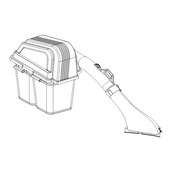
Summary of Contents for Husqvarna 587 96 04-01
- Page 1 GRASS CATCHER Operator / Parts Manual 587 96 04-01 46" / 2 BAG Please read the operator manual carefully and make sure you understand the instructions before using the machine.
- Page 2 KNOW YOUR GRASS CATCHER CONGRATULATIONS on the purchase of a new collection system. It has been designed, engineered and manufactured READ THIS OPERATION MANUAL AND SAFETY RULES to give the best possible dependability and performance. BEFORE ASSEMBLING OR OPERATING YOUR COLLECTION SYSTEM.
-
Page 3: Tips For Improved Bagging
CONTENTS SAFETY ............. 4 ASSEMBLY ............6 PARTS ............. 10 Tips For Improved Bagging • Plastic trash bags (3.0 mil, 30 gallon) can be inserted inside • Follow the mower operation instructions in the Operator grass catcher containers for ease of debris disposal. To Manual. -
Page 4: Slope Operation
SAFETY Slope Operation Slopes are a major factor related to loss-of-control and tip-over WARNING! THIS CUTTING MACHINE IS CAPABLE accidents, which can result in severe injury or death. All slopes OF AMPUTATING HANDS AND FEET AND THROWING require extra caution. If you cannot back up the slope or if you OBJECTS. - Page 5 ASSEMBLY TOOLS REQUIRED CONTAINER CONTENTS • Ft/Lbs Torque Wrench • Wrench ½" (2) • Bagger Assembly • Cover Assembly • Socket and Ratchet " • Wrench " (2) • Upper Chute • Lower Chute • Standard Screwdriver • Wrench " (2) •...
- Page 6 ASSEMBLY MOUNTING COVER ASSEMBLY CONTAINER INSTALLATION 1. Install containers on support frame, overlapping NOTE: Assistance from another person may ease mounting the containers at center tube. cover assembly to mower. 1. Position cover assembly on the ground behind the mower. NOTE: One container should always overlap the other container at the center tube. 2. Lift and rotate cover to align the frame bracket with the hanger and slide the cover down until secure. 2. Close cover and lock latch handle over support tubes.
- Page 7 ASSEMBLY HOOD SEAL INSTALLATION 4. Reattach the deflector to the new bracket assembly with the replacement pin and bowtie clip from the kit. 1. Install the grommet into hood assembly, making sure grommet is seated correctly and securely. It is recommended to use a box pattern as shown when drilling holes. 2. While holding the grommet securely in place, drill one (.203) diameter hole through the grommet and hood assembly at a distance of ¼" (.250) from the outside edge of the grommet. See illustration. All models - use Step 5 5. Lift the deflector up and set the lower chute over the front tab on the bracket assembly and hook the chute latch assemblies onto the tabs on the deck ridge. 3. Locate the seal fastening kit (packaged separately). Install hardware using configuration shown before drilling the next hole. Repeat the procedure with each remaining hole. Deflector Bracket Tab Latch Assembly 6. Slide upper chute onto lower chute, lining up notches and channels. 7. Stretch bungee latch up onto acorn nut on upper chute to CHUTE / HOOD INSTALLATION secure.
-
Page 8: Repair Parts
REPAIR PARTS... - Page 9 REPAIR PARTS ITEM PART NO. QTY. DESCRIPTION ITEM PART NO. QTY. DESCRIPTION 11.. 539 10 80-96 ..1 ..HAIRPIN, RETAINER 1.. 539 11 11-39 ..1 ..COVER ASSY, COMPLETE 12.. 539 10 80-97 ..3 ..CAP, TUBING END 2.. 532 40 02-26 ..2 ..CONTAINER, SOFT BAG 13..
- Page 10 REPAIR PARTS...
- Page 11 REPAIR PARTS ITEM PART NO. QTY. DESCRIPTION ITEM PART NO. QTY. DESCRIPTION 1.. 525 49 70-01 ..1 ..CHUTE, UPPER 18.. 588 71 04-01 ..1 ..PIN 2.. 532 40 54-55 ..1 ..CHUTE, LOWER 19.. 532 11 04-52 ..1 ..PUSHNUT 3..
- Page 12 P/N 115 74 17-27 Rev B 2015-03-15...


