Advertisement
Quick Links
SERVICE MANUAL
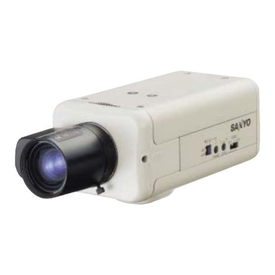
B/W CCD Camera
SPECIFICATIONS
Scanning system : CCIR standard (625 TV lines, 25 frames/sec.)
Interlace : PPL 2:1 interlace
Image device : 1/3 inch solid state image device CCD
Number of pixels in image area : 500 (Horizontal) x 582 (Vertical)
Synchronizing system : Internal sync/ Line lock (only when using an AC
power supply)
Resolution : 400 TV lines
Video output terminal : 1.0 Vp-p/75 Ω, composite
Image S/N ratio : More than 50 dB
Minimum required illumination : Approx. 0.05 lx (F 1.2 lens)
Backlight compensation : ON/OFF
Lens iris output terminal : 4-pin
Lens mount : CS mount
Flange-back : 12.5 mm ± 0.5 mm
Lens setting : EI/VIDEO/DC
Operating environment : Temperature: -10 − + 50 °C (14°F − 122 °F)
Humidity: less than 90 % RH (no condensation)
Power supply : AC 24 V ± 10% 50Hz, DC 12 − 15 V
Power consumption : Approx. 3.0W
Weight : Approx. 245 g
The components designated by a symbol (
special significance to product safety. Should any component designated by a symbol need to be replaced, use only the
part designated in the Parts List. Do not deviate from the resistance, wattage, and voltage ratings shown.
NOTE : 1. Parts order must contain model number, part number, and description.
2. Substitute parts may be supplied as the service parts.
3. N. S. P. : Not available as service parts.
Design and specification are subject to change without notice.
L73S2/XE,XE2
PRODUCT SAFETY NOTICE
) in this schematic diagram designates components whose value are of
FILE NO.
VCB-3455P
(Product Code : 117 074 27)
(Product Code : 117 074 30)
(Europe, U.K., Russia)
(Asia, Mideast, China)
(Australia, New Zealand)
CONTENTS
1. DISASSEMBLY ....................................2
2. BOARD LOCATION .............................3
3. ADJUSTMENT .....................................4
4. PARTS LIST .........................................5
CIRCUIT DIAGRAMS & PRINTED
WIRING BOARDS ..................................C1
REFERENCE No. SM5310604
Advertisement

Summary of Contents for Sanyo VCB-3455P
-
Page 1: Specifications
FILE NO. SERVICE MANUAL B/W CCD Camera VCB-3455P (Product Code : 117 074 27) SPECIFICATIONS (Product Code : 117 074 30) (Europe, U.K., Russia) (Asia, Mideast, China) Scanning system : CCIR standard (625 TV lines, 25 frames/sec.) Interlace : PPL 2:1 interlace... - Page 2 1. DISASSEMBLY 1.Remove the six screws 3.Remove rear cover 2.Remove the six screws and pull out the rear cover 4.Remove the two screws 5.Remove the lens cap 6.Remove the two screws 7.Remove the two screws and pull out the front cover 8.Remove the four screws and remove the main board 10.Remove the two screws...
-
Page 3: Board Location
2. BOARD LOCATION P001 SENSOR BOARD S102 VR103 VR104 VR102 P105 P103 T102 VL101 P104 MAIN BOARD SENSOR BOARD MAIN BOARD − 3 −... - Page 4 3. ADJUSTMENT 3-1. ADJUSTMENT PREPARATION 1. Use the 3,200K viewer for the subject. 2. Set the ITE gray scale chart II (γ =0.45) to the viewer. 3. Set the angle of adjustment control (VR) before starting adjustment at the center or temporary adjustment (nearly adjusted) unless specified.
-
Page 5: Parts List
4. PARTS LIST ELECTRICAL PARTS Note: 1. Capacitors UF : µF PF : pF 2. Inductors UH : µH MH : mH 3. N.S.P. : Not available as service parts. LOCATION PARTS NO. DESCRIPTION LOCATION PARTS NO. DESCRIPTION C006 SENSOR+MAIN BOARD C130 TCZE63-4247520 TANTALUM CAPACITOR 47UF,6.3V (B) C132... - Page 6 LOCATION PARTS NO. DESCRIPTION LOCATION PARTS NO. DESCRIPTION D103 TCZE02-0015951 DIODE 1SR159-200 (RECTITIER DIODE) R163 TCZE61-4624300 RESISTANCE 24K D104 TCZE02-0015951 DIODE 1SR159-200 (RECTITIER DIODE) R164 TCZE61-4622300 RESISTANCE 22K OHM 0603 1% D105 TCZE02-0516051 DIODE RB160-40 R165 TCZE61-4616302 RESISTANCE 16K OHM 0603 (SCHOTTKY BARRIER DIODE) R166 TCZE61-4620300 RESISTANCE 20.5K OHM 0603 1%...
- Page 7 P103 TCZE76-0818050 CONNECTOR FH12-18S-0.5 SV (N.S.P.) (MISCELLANEOUS) TCZM50-0722000 BOSS MH4.8*4A FLEXIBLE FLAT CABLE TCZE79-1902040 CABLE HOUSING 40MM 2PIN FOR SANYO TCZE79-5018030 CABLE FFC 18PIN P0.5 30MM S300/S400 ACCESSORIES & PACKING MATERIALS TCZE82-0001010 EMI CORE TCZEIM-0010423 INSTRUCTION MANUAL (ENGLISH/FRENCH) TCZEIM-0010424 INSTRUCTION MANUAL...
- Page 8 CABINET & CHASSIS PARTS VCB-3455P...
- Page 9 SANYO Electric Co., Ltd. Osaka, Japan Printed in Japan Oct./’04...


