Advertisement
Quick Links
Download this manual
See also:
Technical Manual
FDUL221
en
Line tester – operating instructions for electricians
1. Intended use
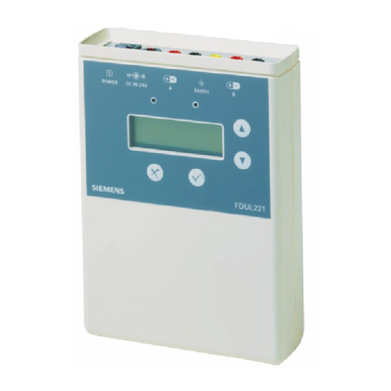
The FDUL221 line tester is used to diagnose an addressed detector line in FDnet/C-NET. During diagnosis, the detector line
must not be connected to the control panel.
This document contains all necessary information on the FDUL221 line tester in the 'EL' operation mode. The 'EL' operation
mode is only intended for use by electricians. The electrician has received specialist training in the area of building installation
technology or electrical installations.
2. Control and connection elements
Item
Symbol/element
1
2
3
4
5
6
7
8
9
10
11
12
A6V10395483_b_en_--
2014-05-14
Description
Function
Adjustable backlight and contrast
Display
Scrolling plain text and symbol display
Flashes slowly in the event of an error during startup
LED red
Flashes rapidly when PC is connected
Flashes faintly during normal operation
Flashes brightly when reading in the line topology or when PC is
LED green
connected
Lights up when scrolling
Buttons
Scrolling (up/down) between the menus and within the menus
Up/down
Scrolling (right/left) within a function, e.g. in Device Info or in LCD Setup
Confirming a selection, e.g. entering a menu or a function
OK button
Starting a procedure, e.g. activating tests
Activating a function, e.g. switching relays, sounds and alarm indicators
Quitting a function or a menu
Exit button
Cancelling a procedure
Starting the 'Configuration' menu tree (together with the on/off) switch
B (+) red
Connection for line end for a loop
B (-) black
A (+) red
Connection for line start for a loop/stub and for a single line device
A (-) black
External power supply via the supplied FDUL221-B power unit (DC 24 V,
Socket
625 mA)
Switch
I = On
'On/off'
O = Off
Socket
Connection for the ground wire or shielding
'Yellow/green'
USB connection
Connection to PC (in the case of older FDUL221 line testers also RS232
type B
interface or MC link)
Building Technologies
Control Products and Systems
Advertisement

Summary of Contents for Siemens FDUL221
- Page 1 Line tester – operating instructions for electricians 1. Intended use The FDUL221 line tester is used to diagnose an addressed detector line in FDnet/C-NET. During diagnosis, the detector line must not be connected to the control panel. This document contains all necessary information on the FDUL221 line tester in the 'EL' operation mode. The 'EL' operation mode is only intended for use by electricians.
- Page 2 Ground fault 4. Power supply (DC 24 V, 625 mA) lithium The power supply is provided either by the supplied FDUL221-B power unit or two batteries (type: manganese dioxide type U9VL Li/MnO 9 V, 1 Ah). 5. Connecting the detector line to the line tester...
- Page 3 Operating instructions for electricians 6. Description of the line topology The line devices are displayed in the order of the loop/stub. On the branch to the sub-stub, the line devices are displayed in the order of the sub-stub. The display shows the number of the line device in brackets. E.g.
-
Page 4: Operation Mode
Operating instructions for electricians 7. Navigating the menu tree in the 'EL' operation mode To open the 'Configuration' menu tree, switch the line tester The figure below shows the structure of a menu tree and the on while pressing and holding the button. - Page 5 Technical manual 008250 on the FDUL221 line tester. 'Locate devices' menu. 12. Table of faults Below you will find an overview of the errors displayed by the FDUL221 line tester as well as possible causes and remedies for the errors. = Line device...
- Page 6 Operating instructions for electricians Error Possible cause Remedy Open line in the line. The exact position of the open line Check the cable. Search for the faulty location cannot be identified by the line tester. by disconnecting the detector line and re- checking the cable connection.
- Page 7 Operating instructions for electricians Error Possible cause Remedy A sub-stub is not permitted in this location. A branch is not allowed. Change the wiring. Ensure that a 'Sub-stub on stub' topology has Note: This error number indicates several line devices as faulty. not been wired.
- Page 8 Take this into account when analyzing the measurement. You will find more information on the FDUL221 line tester in the Technical manual 008250. The 'PC Linetester Tool FXS2017' software offers optimum display and control options for the FDUL221 line tester.


