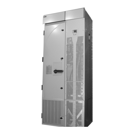
Summary of Contents for ABB ACS550-U2
- Page 1 Drive Low Voltage AC Drives Installation Supplement ACS550-U2 Drives (150…550 HP)
- Page 2 Installation Supplement for ACS550-U2 Drives ACS550 Drive Manuals GENERAL MANUALS ACS550-01/U1 User's Manual (0.75…90 kW) / (1…150 HP) • Safety • Installation • Start-Up • Diagnostics • Maintenance • Technical Data ACS550-02/U2 User's Manual (110…355 kW) / (150…550 HP) • Safety •...
-
Page 3: Safety
Installation Supplement for ACS550-U2 Drives Safety General In this manual, ACS550 refers, unless otherwise stated, to type ACS550-U2. Warning! The ACS550 adjustable speed AC drive should ONLY be installed by a qualified electrician. Warning! Even when the motor is stopped, dangerous voltage is present at the Power Circuit terminals U1, V1, W1 and U2, V2, W2 and UDC+, UDC-. -
Page 4: Table Of Contents
Installation Supplement for ACS550-U2 Drives Table of Contents Safety General ............3 Use of Warnings and Notes . -
Page 5: Installation
Ignoring the safety instructions can cause injury or death. Planning When planning for cable/conduit routing, refer to the ACS550-02/U2 User’s Manual, but note that, for the ACS550-U2, all connections are routed through the top of the extension module. Moving the Unit 1. -
Page 6: Mounting
There are two holes available at the top of each: the extension module and the drive module. Connecting Power and Control Cables Additional considerations that apply with the enclosure extension: • The power cable connection diagram that applies for the ACS550-U2 is: ACS550-02 Extension Module Drive Module... - Page 7 Installation Supplement for ACS550-U2 Drives • Route all power and control wiring through the top of the extension module. • The following diagram shows the power and control connection points in the enclosure module supplied with the R7 drive module.
- Page 8 Installation Supplement for ACS550-U2 Drives • The following diagram shows the power and control connection points in the enclosure module supplied with the R8 drive module. R8 Frame Size Gland/Conduit Plate (Cable fittings shown are typical examples) PE Connection Output (U2,V2,W2)
-
Page 9: Maintenance
Installation Supplement for ACS550-U2 Drives Maintenance This section describes the procedure for separating the drive and extension modules, which is required to provide service access to the drive module. Safety WARNING! Read "Safety" on the first pages of this manual before performing any maintenance on the equipment. - Page 10 Installation Supplement for ACS550-U2 Drives 7. The following cables between the drive and the extension module are split by a connector located at the front of the drive. Disconnect both cables at this location. • The power supply cable to the OMIO board.
-
Page 11: Technical Data
Installation Supplement for ACS550-U2 Drives Technical Data Dimensional Drawings See the ACS550-02/U2 User’s Manual for drive module dimensions. Extension Module R7 Dimensions are listed in millimeters and [inches] 3AFE 64626264 30.04.02 Technical Data... - Page 12 Installation Supplement for ACS550-U2 Drives Detail Dimensions are listed in millimeters and [inches] Technical Data...
- Page 13 Installation Supplement for ACS550-U2 Drives Extension Module R8 Dimensions are listed in millimeters and [inches] 3AFE 64626388 30.04.02 US gland/conduit Technical Data...
- Page 14 Installation Supplement for ACS550-U2 Drives Detail Dimensions are listed in millimeters and [inches] Technical Data...
- Page 15 Installation Supplement for ACS550-U2 Drives Technical Data...
- Page 16 ABB Oy ABB Inc. AC Drives Automation Technologies P.O. Box 184 Drives & Machines FIN-00381 HELSINKI 16250 West Glendale Drive FINLAND New Berlin, WI 53151 Telephone +358 10 22 11 Telefax +358 10 22 22681 Telephone 262 785-3200 Internet http://www.abb.com...


