Table of Contents
Advertisement
Quick Links
Advertisement
Table of Contents

Summary of Contents for Bosch D7039
- Page 1 D7039 Installation Guide Multiplex Expansion Module...
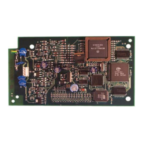
- Page 2 Notices Description Use these instructions to install the D7039 Multiplex The D7039 (Figure 1) connects directly to the FACP for Expansion Module in a fire system supervised by a either two Class B multiplex buses or one Class A D7024 Fire Alarm Control Panel (FACP).
- Page 3 6. Mount the D7039 on the standoffs, ensuring the FACP connector pins (Item 4 in Figure 2) are properly aligned. Install the FACP in the enclosure. 8. Use the mounting screw (Item 5 in Figure 2) to secure the D7039’s ground wire (Item 6 in Figure 2) to the FACP. Figure 2: Mounting the D7039 on the D7024...
- Page 4 2.0 Installation D7039 | Installation Guide | 9. Mount the D7039 I/O Module (Item 1 in Figure 3) in the FACP enclosure (Item 2 in Figure 3) using the mounting holes in the enclosure (Item 3 in Figure 3). 10. Connect the yellow and green earth ground wire from the I/O module to the earth ground terminal on the FACP control board (Item 4 in Figure 3).
- Page 5 D7039 | Installation Guide | 4.0 Specifications You can configure the D7039 with a single fault tolerant Class “A” loop or as a pair of supervised Class “B” loops. When configured as a Class “A” loop and installed on a D7024 Control Panel before Lot #100, the D7039 implements a Style 4.5 signaling line circuit (SLC).
-
Page 6: Specifications
D7039 | Installation Guide |Notes Specifications Table 1: Specifications Input Voltage 24 VDC nominal from FACP 150 mA maximum Current Draw, Standby and Alarm Current Draw Load 100 mA maximum for each bus 8.5 V to 13 V Maximum Bus Voltage 50 Ω, Class A (Style 6) or Class B (Style 4) SLC... - Page 7 D7039 | Installation Guide | Notes Notes Bosch | 09/05 | 38685F...
- Page 8 Bosch 130 Perinton Parkway Fairport, NY 14450-9199 USA Customer Service: (800) 289-0096 Technical Support: (888) 886-6189 © 2005 Bosch 38685F...


