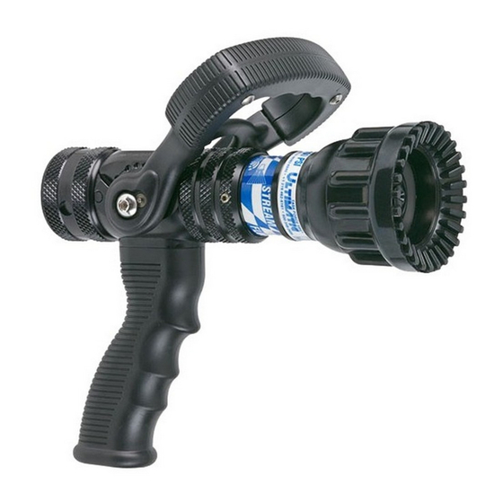
Task Force Tips ULTIMATIC Instructions For Safe Operation And Maintenance
Hand held automatic pressure control nozzles
Hide thumbs
Also See for ULTIMATIC:
- Instructions for installation, operation and maintenance (8 pages) ,
- Manual (24 pages) ,
- Instructions for installation, safe operation and maintenance (12 pages)
Table of Contents
Advertisement
Quick Links
ULTIMATIC,
ULTIMATIC,
INSTRUCTIONS FOR SAFE OPERATION AND MAINTENANCE
WARNING
WARNING
WARNING
HANDLINE
TASK FORCE TIPS, Inc.
Made in USA • www.tft.com
©Copyright Task Force Tips, Inc. 2002-2008
TFT HAND HELD AUTOMATIC
PRESSURE CONTROL NOZZLES
MID-MATIC
Read instruction manual before use. Operation of this nozzle without
understanding the manual and receiving proper training can be dangerous and is
a misuse of this equipment. Call 800-348-2686 with any questions.
This instruction manual is intended to familiarize firefighters and maintenance
personnel with the operation, servicing and safety procedures associated with
the Ultimatic, Mid-Matic and Handline fire fighting nozzles.
This manual should be kept available to all operating and maintenance
personnel.
ULTIMATIC
& HANDLINE
2351 Industrial Drive • Valparaiso , IN 46383-9511 USA
800-348-2686 • 219-462-6161 • Fax 219-464-7155
MID-MATIC
LIN-030 November 14, 2008 Rev 10
Advertisement
Table of Contents

Summary of Contents for Task Force Tips ULTIMATIC
- Page 1 This instruction manual is intended to familiarize firefighters and maintenance personnel with the operation, servicing and safety procedures associated with the Ultimatic, Mid-Matic and Handline fire fighting nozzles. WARNING This manual should be kept available to all operating and maintenance personnel.
-
Page 2: Table Of Contents
4.2.2 FLUSH CONTROL5 4. It is your responsibility to be in proper physical condition and to maintain the personal skill level required to operate any equipment you may be 5.0 USE OF ULTIMATIC, MIDMATIC & HANDLINE called upon to use. NOZZLES 5. -
Page 3: General Information
2.0 GENERAL INFORMATION The Task Force Tips Ultimatic, MID-MATIC and Handline nozzles are designed to provide excellent performance under most fire fighting conditions. Their rugged construction is compatible with the use of fresh water (see section 5.0 for saltwater use) as well as fire fighting foam solutions. Other important operating features are:... -
Page 4: Color Coded Valve Handle Covers Mid-Matic & Handline Only
Preconnect or discharge #6 Black Preconnect or discharge #7 Green Foam Lines Red w/ White border (Red/White) 3.0 FLOW CHARACTERISTICS The graphs in figure 2 show the typical performance of ULTIMATIC, MID-MATIC and HANDLINE nozzles. FLOW (LPM) 1000 1200 ULTIMATIC FLOW RANGE MID-MATIC... -
Page 5: Nozzle Controls
100 120 140 160 180 200 220 260 280 FLOW (GPM) 75 PSI ULTIMATIC, MID-MATIC & HANDLINE FIGURE 2 The charts in section 8.0 of this document give specific examples of maximum flow rates for particular situations. Friction losses may vary due to differences in hose construction resulting in flows different than those shown. For situations or lengths of hose not listed on the chart, approximate flows can be calculated using conventional hydraulics. -
Page 6: Twist Shutoff
4.2 PATTERN AND FLUSH CONTROL 4.2.1 PATTERN CONTROL TFT's ULTIMATIC, MID-MATIC and HANDLINE have full pattern control from straight stream to wide fog. Turning the STREAM SHAPER clockwise (as seen from the operating position behind the nozzle) moves the SHAPER to the straight stream position. -
Page 7: Use Of Ultimatic, Midmatic & Handline Nozzles
Performance tests shall be conducted on the Ultimatic, Mid-Matic and Handline nozzle after a repair, or anytime a problem is reported to verify operation in accordance with TFT test procedures. Consult factory for the procedure that corresponds to the model and serial number of the nozzle. -
Page 8: Warranty
("TFT") warrants to the original purchaser of its Ultimatic, Mid-Matic, and Handline series nozzles ("equipment"), and to anyone to whom it is transferred, that the equipment shall be free from defects in material and workmanship during the five (5) year period from the date of purchase. -
Page 9: Nozzle Flow Charts
(3) Flows are approximate and do not reflect losses in preconnect piping. (4) 1 BAR = 100 KPA (3) Flows are approximate and do not reflect losses in preconnect piping. (4) 1 BAR = 100 KPA ©Copyright Task Force Tips, Inc. 2002-2008 LIN-030 November 14, 2008 Rev 10... - Page 10 (2) Flows may vary with brand or condition of hose. (3) Flows are approximate and do not reflect losses in preconnect piping. (2) Flows may vary with brand or condition of hose. (3) Flows are approximate and do not reflect losses in preconnect piping. ©Copyright Task Force Tips, Inc. 2002-2008 LIN-030 November 14, 2008 Rev 10...
- Page 11 (2) Flows may vary with brand or condition of hose. (3) Flows are approximate and do not reflect losses in preconnect piping. (2) Flows may vary with brand or condition of hose. (3) Flows are approximate and do not reflect losses in preconnect piping. ©Copyright Task Force Tips, Inc. 2002-2008 LIN-030 November 14, 2008 Rev 10...
-
Page 12: Inspection Checklist
Shaper turns freely and adjusts pattern through full range. Shaper turns into full flush and out of flush with normal flow and pressure restored. Any Ultimatic, Mid-Matic or Handline nozzle failing any part of the WARNING inspection checklist is unsafe and must have the problem corrected before use.


