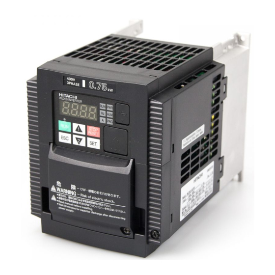
Hitachi WJ200 Installation Manual
Hide thumbs
Also See for WJ200:
- Instruction manual (421 pages) ,
- Quick reference manual (131 pages) ,
- Software manual (15 pages)
Summary of Contents for Hitachi WJ200
- Page 1 Electromagnetically Compatible Installation Guide Book Inverter Series WJ200 Hitachi Europe GmbH...
-
Page 2: Table Of Contents
CHAPTER 3 – INFLUENCE OF THE MOTOR CABLE LENGTH ....... 3-1 CHAPTER 4 – FURTHER NOTES................4-1 ............ 4-1 NFLUENCE OF GROUND FAULT MONITORING DEVICES ............... 4-1 OMPONENTS SUSCEPTIBLE TO INTERFERENCE CHAPTER 5 – TECHNICAL SPECIFICATIONS AND DIMENSIONS OF WJ200 FILTER ......................5-1 CHAPTER 6 –HARMONICS ..................6-1... -
Page 3: Chapter 1 - Warnings And Instructions
WARNING The Hitachi WJ200 series is not intended for sales to general public but a professional equipment to be used in trades, professions and industries. If installed according to the following directions, the frequency inverter comply with the... -
Page 4: Chapter 2 - Electromagnetically Compatible
Chapter 2 – Electromagnetically compatible installation of drives and drive systems Chapter 2 – Electromagnetically Compatible Installation of Drives and Drive Systems Introduction This brochure describes the electromagnetically compatible setup of your drive or your drive system. (Electro Magnetic Compatibility = EMC) Read this information carefully and follow the instructions. -
Page 5: Selection Of Line Filter To Reduce Line-Conducted Interference
To reduce line-conducted interference, use the appropriate line filter for each frequency inverter. The table below show you a list of the available line filters for your Hitachi frequency inverter. The all line filters are built in the so-called footprint style, are fitted behind the respective frequency inverter, and thus require no additional space for installation. -
Page 6: Filter Installation
Chapter 2 – Electromagnetically compatible installation of drives and drive systems Filter installation The connecting cable between filter and frequency inverter must be as short as possible and laid separate from other cables/lines. As user you must ensure that the HF impedance between frequency inverter, filter and ground is as small as possible: ... - Page 7 Inverter carrier frequency Frequency inverter Category C1 25m Max. 10kHz WJ200-002,004,007,015,022SF Category C2 50m Max. 10kHz *1: The inverter needs to be installed in a metal cabinet to meet category C1. Otherwise category C2. Filter: FPF-9340-05-SW, FPF-9340-10-SW, FPF-9340-14-SW, FPF-9340-30-SW, FPF-9340-50-SW...
-
Page 8: Minimizing Radiated Interference
Chapter 2 – Electromagnetically compatible installation of drives and drive systems Minimizing radiated interference The frequency inverter of series WJ200 meet the limits of EN61800-3, C1/C2/C3, for radiated interference, if the specified line filter is used and installation is performed according to our instructions. -
Page 9: Using Emc Compliant Cables
Chapter 2 – Electromagnetically compatible installation of drives and drive systems Using EMC compliant cables In order to reduce electromagnetic emission caused by motor cables and to increase EMI immunity for control cables, shielded cables have to be used. Using this shielding can reduce the interference coupled into and out of the cable (please also refer to the previous chapter „Minimizing radiated interference“). -
Page 10: Installing The Motor Cable
Chapter 2 – Electromagnetically compatible installation of drives and drive systems Installing the motor cable If you use an EMC line filter or would like to observe certain limits of line-conducted interference, the motor cable which you use must be shielded. The shield is to be grounded on both sides, over a large area. -
Page 11: Shielding And Grounding For Installation In Switch Cabinets
Observe the requirements of European standard EN60204-1, "Electrical Equipment of Industrial Machinery." You get optimum EMC only if you properly arrange and mount the Hitachi frequency inverter, the appropriate line filter, and the other equipment which might be necessary, on a metal mounting plate in accordance with the following mounting instructions. - Page 12 Chapter 2 – Electromagnetically compatible installation of drives and drive systems The following figure shows the required EMC compliant connection to the motor: good HF-connection between required EMC-cable connection heat sink and motor housing metall box W PE...
-
Page 13: Chapter 3 - Influence Of The Motor Cable Length
Chapter 3 – Influence of the motor cable length Chapter 3 – Influence of the Motor Cable Length Shielded motor cables have quite a high cable capacity towards ground, which increases linearly as cable length increases. A typical rule-of-thumb figure is 200 pF per meter of cable. But these figures vary among different types of cables and are also dependent on the current-carrying capacity. -
Page 14: Chapter 4 - Further Notes
Chapter 4 – Further Notes Chapter 4 – Further Notes Influence of ground fault monitoring devices In the line filter, capacitors are placed between the phases and ground, which can cause larger charge currents to flow to ground when the filter is first switched on. The amount of this flow has already been minimized by constructional circuit details. -
Page 15: Chapter 5 - Technical Specifications And Dimensions Of Wj200 Filter
Chapter – Technical specifications and dimensions of WJ200 filter Chapter 5 – Technical Specifications and Dimensions of WJ200 Filter Type: FPF- FPF-9120-10-SW FPF-9120-14-SW FPF-9120-24-SW Specification: Voltage in V 240 +5% 240 +5% 240 +5% Current in A at 40°C 2 x 8A... - Page 16 Chapter – Technical specifications and dimensions of WJ200 filter Current at 40°C ambient temperature Overload 1.5 x I N for 3min Frequency 50 / 60 Hz Material Metal housing Humidity class IEC-Clamate-Category acc. to IEC60068-1: 25/100/21...
- Page 17 Chapter – Technical specifications and dimensions of WJ200 filter FPF-9120-10-SW FPF-9120-14-SW/ FPF-9120-24-SW...
- Page 18 Chapter – Technical specifications and dimensions of WJ200 filter FPF-9340-05-SW/ FPF-9340-10-SW FPF-9340-14-SW...
- Page 19 Chapter – Technical specifications and dimensions of WJ200 filter FPF-9340-30-SW FPF-9340-30-SW...
-
Page 20: Chapter 6 -Harmonics
Ssc greater than or equal to the value mentioned in the table below. AC/DC Inverter model Norm Rsce reactor WJ200-001/002SF EN/IEC61000-3-2 WJ200-055HF 1663kVA >120 3% AC choke WJ200-075HF 1996kVA >120...


