Table of Contents
Advertisement
Quick Links
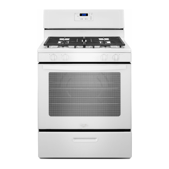
30" (76.2 CM) FREESTANDING GAS RANGES
IMPORTANT:
Save for local inspector's use.
Installer: Leave installation instructions with the homeowner.
Homeowner: Keep installation instructions for future reference.
W10620413E
INSTALLATION INSTRUCTIONS
Table of Contents
RANGE SAFETY...................................................................................2
INSTALLATION REQUIREMENTS .....................................................3
Tools and Parts..................................................................................3
Location Requirements .....................................................................4
Electrical Requirements.....................................................................5
Gas Supply Requirements ................................................................6
INSTALLATION INSTRUCTIONS .......................................................7
Unpack Range...................................................................................7
Install Anti-Tip Bracket ......................................................................7
Make Gas Connection.......................................................................8
Verify Anti-Tip Bracket Is Installed and Engaged .............................9
Level Range .....................................................................................10
Electronic Ignition System...............................................................10
Complete Installation.......................................................................12
GAS CONVERSIONS .........................................................................12
LP Gas Conversion..........................................................................12
Complete Conversion......................................................................14
Natural Gas Conversion ..................................................................14
Complete Conversion......................................................................16
Advertisement
Table of Contents

Summary of Contents for Whirlpool WFG320M0BW0
-
Page 1: Table Of Contents
INSTALLATION INSTRUCTIONS 30" (76.2 CM) FREESTANDING GAS RANGES Table of Contents RANGE SAFETY...................2 INSTALLATION REQUIREMENTS .............3 Tools and Parts..................3 Location Requirements ..............4 Electrical Requirements..............5 Gas Supply Requirements ..............6 INSTALLATION INSTRUCTIONS ............7 Unpack Range...................7 Install Anti-Tip Bracket ..............7 Make Gas Connection...............8 Verify Anti-Tip Bracket Is Installed and Engaged ......9 Level Range ..................10 Electronic Ignition System...............10... -
Page 2: Range Safety
RANGE SAFETY Your safety and the safety of others are very important. We have provided many important safety messages in this manual and on your appliance. Always read and obey all safety messages. This is the safety alert symbol. This symbol alerts you to potential hazards that can kill or hurt you and others. All safety messages will follow the safety alert symbol and either the word “DANGER”... -
Page 3: Installation Requirements
In the State of Massachusetts, the following installation instructions apply: ■ Installations and repairs must be performed by a qualified or licensed contractor, plumber, or gasfitter qualified or licensed by the State of Massachusetts. ■ If using a ball valve, it shall be a T-handle type. ■... -
Page 4: Location Requirements
Location Requirements IMPORTANT: Observe all governing codes and ordinances. Do Mobile Home - Additional Installation Requirements not obstruct flow of combustion and ventilation air. The installation of this range must conform to the Manufactured Home Construction and Safety Standard, Title 24 CFR, Part 3280 ■... -
Page 5: Electrical Requirements
Cabinet Dimensions Electrical Requirements Cabinet opening dimensions shown are for 25" (64.0 cm) WARNING countertop depth, 24" (61.0 cm) base cabinet depth and 36" (91.4 cm) countertop height. If the cabinet depth is greater than 24" (61.0 cm), oven frame must extend beyond cabinet fronts by ½"... -
Page 6: Gas Supply Requirements
Gas Supply Requirements WARNING Gas Supply Line ■ Provide a gas supply line of ¾" (1.9 cm) rigid pipe to the range location. A smaller size pipe on longer runs may result in insufficient gas supply. With LP gas, piping or tubing size can be ½"... -
Page 7: Installation Instructions
Burner Input Requirements Gas Supply Pressure Testing Input ratings shown on the model/serial rating plate are for Gas supply pressure for testing regulator must be at least elevations up to 2,000 ft (609.6 m). 1" water column pressure above the manifold pressure shown on the model/serial rating plate. -
Page 8: Make Gas Connection
3. Determine and mark centerline of the cutout space. The mounting can be installed on either the left side or right side Make Gas Connection of the cutout. Position mounting bracket against the wall in the cutout so that the V-notch of the bracket is 9⁵⁄₈" (24.6 cm) WARNING from centerline as shown. -
Page 9: Verify Anti-Tip Bracket Is Installed And Engaged
Complete Connection 5. Remove cooktop burner caps and grates from parts package. Align notches in burner caps with pins in burner 1. Locate gas pressure regulator in the back of the range. base. Burner caps should be level when properly positioned. If burner caps are not properly positioned, surface burners will not light. -
Page 10: Level Range
3. If the rear of the range lifts more than ½" (1.3 cm) off the floor without resistance, stop tilting the range and lower it gently Electronic Ignition System back to the floor. The range foot is not engaged in the anti-tip Initial lighting and gas flame adjustments bracket. - Page 11 If the low flame needs adjusting: If the flame needs adjusting: 1. Turn control knob to the “LOW” setting and remove control 1. Turn the oven off. Wait for the oven burner to cool down. knob. 2. Open oven door and remove oven racks and oven tray and 2.
-
Page 12: Complete Installation
Complete Installation 1. Check that all parts are now installed. If there is an extra part, ■ Range is plugged into a grounded 3 prong outlet. go back through the steps to see which step was skipped. ■ Gas pressure regulator shutoff valve is in the “on” position. 2. - Page 13 To Convert Gas Pressure Regulator To Convert Surface Burners 1. Open broiler door and remove broiler rack. The gas pressure 1. Remove burner grate, burner caps and burners. regulator is located in the back right hand corner of the broiler compartment.
-
Page 14: Complete Conversion
NOTE: The range cooktop is equipped with 4 burners: 6. Place Natural gas oven burner spud in plastic parts bag along 2 burners are power (front), 1 burner is standard (left rear), with Natural gas cooktop burner spuds for future use and and 1 is simmer (right rear). - Page 15 To Convert Gas Pressure Regulator To Convert Surface Burners 1. Open broiler door and remove broiler rack. The gas pressure 1. Remove burner grate, burner caps and burners. regulator is located in the back right hand corner of the broiler compartment.
-
Page 16: Complete Conversion
NOTE: The range cooktop is equipped with 4 burners: 3. Locate Natural gas orifice spud stamped “47” in the bag 2 burners are power (front), 1 burner is standard (left rear), containing literature supplied with the range. and 1 is simmer (right rear). 4.


