Table of Contents
Advertisement
Quick Links
Advertisement
Table of Contents

Summary of Contents for ECM G100
- Page 1 ™ G100 Air-Fuel Ratio Gauge Instruction Manual 6/03 Part Number G100-15...
- Page 2 No part of this manual may be photocopied or reproduced in any form without prior written consent from ECM: ENGINE CONTROL AND MONITORING. Information and specifications subject to change without notice. G100 is a trademark of Engine Control and Monitoring. Printed in the United States of America.
-
Page 3: Table Of Contents
Table of Contents Introduction The G100 Air-Fuel Ratio Gauge G100 Components List Important Operation Notes Installing the G100 Gauge and Record/Playback Control Pod (Option “R”) Control Module and Power Cable Air-Fuel Ratio Sensor and Cable Analog Output (Option “A”) Calibration... - Page 4 Safety Warnings Warranty and Disclaimers...
-
Page 5: Introduction
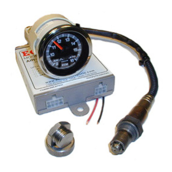
AFR sensor, a 270-degree sweep gauge, data recording with playback, and a linear 0 to 5 volt analog output. Four G100 kits are available: G100C Kit 9.0 to 16.0 AFR (gasoline) -
Page 6: G100 Components List
(with Option “A” only and installed on gauge) Sensor Boss and Plug Kit G100-13 Calibration Screwdriver G100-14 Instruction Manual G100-15 A G100 kit supplied without an AFR sensor is given the suffix “-SD” (sensor delete). Optional adapter cable G100-17H allows use of Honda production sensor. -
Page 7: Important Operation Notes
Important Operation Notes 1. Before installing the AFR sensor, apply a small amount of non-lead containing antiseize compound to its threads. Do not get the compound on the sensor’s tip. 2. Do not operate an engine for more than three minutes with the AFR sensor in the exhaust and the control module’s power disconnected or the “KEY”... -
Page 8: Installing The G100
Installing the G100 The G100 is graphically illustrated below. Installation should proceed in the following order: gauge and record/playback control pod (Option “R”), control module and power cable, AFR sensor and cable, and analog output (Option “A”). Do not modify any of the cables. -
Page 9: Control Module And Power Cable
G100’s control module and other electronics in your vehicle. The wire labeled “KEY” in the power cable is used to turn the G100 on and off. Connect the “KEY” wire to a wire from the ignition switch that is at 12V when the ignition key is in the “Run” position and 0V (or open circuit) when the vehicle’s ignition key if in the “Off”... -
Page 10: Analog Output (Option "A")
(black) of the analog output should be within 0.020 V of battery ground when the G100 is on. Use a voltmeter to make sure this is true when the G100 is on. Also measure the voltage between what the ground wire (black) is about to be connected to (i.e. - Page 11 After the G100 has been calibrated, turn the ignition key off and wait until the sensor has cooled before installing it back into the exhaust. Your G100 is then ready to be used.
-
Page 12: Using The G100
“foot-off-the-gas” deceleration. During fuel shutoff, the G100 will be pinned at 16 AFR (the AFR of air is infinity!). Press the throttle during a fuel shutoff and you will see the AFR come below 16 indicating that the engine is firing again. -
Page 13: Analog Output (Option "A")
During a recording, the voltage output is active and during playback, the analog output will match the replayed AFR. When there is a fault with the G100 and a trouble code is being “flicked” on the gauge, the analog output will be held at 0 V. -
Page 14: Trouble Codes 0
Trouble Codes Trouble codes are indicated by the G100 by “flicking” the needle over the “ECM” logo in the lower area of the gauge. There are five trouble codes (numbered 1 through 5) and they are indicated by the number of “flicks”... -
Page 15: Specifications And Limits
Specifications and Limits Measurement Range and Accuracy Range: 9 to 16 AFR (gasoline) Accuracy: ±2% Exhaust Operating Limits Maximum Exhaust Gas Temperature: 950 deg. C, 1742 deg. F. Exhaust Gas Pressure Range: 0.8 - 1.3 atm (23.9 to 38.9 inches Hg, 81 to 132 kPa). Air-Fuel Ratio Sensor Installation Thread Size: M18X1.5mm. -
Page 16: Troubleshooting
If the G100’s needle is “flicking” a trouble code, refer to the “Trouble Code” section for more information. If you think that the G100 is displaying the wrong AFR value then one of five conditions exists: 1. The G100 needs to be calibrated. See the “Calibration” section in “Installing the G100”. - Page 17 Do not attach the battery until the installation is completed. Never work on a running engine. When installing the G100, it is best to think-out your moves before you make them. Route and cable-tie all cables away from hot, moving, sharp, high energy (spark), and caustic objects.
- Page 18 Warranty and Disclaimers WARRANTY The products described in this manual, with the exception of the AFR sensor, are warranted to be free from defects in material and workmanship for a period of 365 days from the date of shipment to the buyer. Within the 365 day warranty period, we shall at our option replace such items or reimburse the customer the original price of such items which are returned to us with shipping charges prepaid and which are determined by us to be defective.
- Page 21 Los Altos, CA 94023-0040 • USA • (408) 734-3433 • Fax: (408) 734-3432 www.ecm-co.com...


