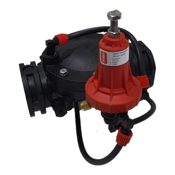
Toro 900 Series Installation Operation & Maintenance
Electric on-off valve
Hide thumbs
Also See for 900 Series:
- Installation, operation & maintenance manual (2 pages) ,
- Installation operation & maintenance (2 pages) ,
- Assembly instruction manual (16 pages)
Advertisement
Quick Links
Ag
Installation Operation Maintenance (IOM)
Manual 900 Series Electric On-Off Valve
Description
The Toro's new 900 series valves have a cutting-edge, patent-pending
hydrodynamic valve seat design that creates an easier path for the water through
the valve, reducing pressure loss and allowing the irrigation system to reach
operational flow rates. The valve opens and closes drip-tight in response to an
electrical signal from the solenoid switch.
1)
Installation
The valve can be installed both horizontally or vertically.
2)
Ensure enough space nearby for installation and adjustment.
3)
Flush the pipeline before installing the valve to ensure clean water flow.
4)
The line flow direction should match the arrow on the valve.
5)
Inspect the valve post installation for any loose or damaged fittings.
6)
Install a pressure gauge upstream or use a pressure checkpoint on the valve to set the desired pressure.
7)
Installing isolation valves upstream and downstream is recommended for maintenance.
8)
Cross-check solenoid specifications with design requirements and solenoid/coil labels.
Initial Startup and Adjustment
1)
Fully open the upstream isolation valve (if installed).
2)
Allow the valve to open by using the solenoid manual override or by giving the electric command to the solenoid.
3)
Slowly open the downstream isolation valve (if installed) and allow the line downstream of the valve to fill up.
4)
Once the system is pressurized, check the valve solenoid control feature by de-energizing or energizing the solenoid to close
or open the valve (AC supply for 3W-24VAC solenoid or pulse signal for latching solenoid, 3W: 9-24 VDC Latch).
Maintenance
1) Regular periodic valve inspection should be done to check for any damage or leakage through valve connection
and fittings.
2) Inspect and clean the in-line finger filter as water quality dictates. This should be done once every few months.
3) Check valve performance by periodically checking the upstream pressure gauge and adjusting it if required.
4) In case the valve requires the replacement of internal worn parts or elastomers, follow the steps below:
a) Disassemble necessary control tubing.
b) Open the screws and remove the cover unit from the valve body.
c) Replace the worn parts and assemble them as before. Ensure to lubricate nuts and bolts with anti-
seize grease.
Advertisement

Summary of Contents for Toro 900 Series
- Page 1 Manual 900 Series Electric On-Off Valve Description The Toro’s new 900 series valves have a cutting-edge, patent-pending hydrodynamic valve seat design that creates an easier path for the water through the valve, reducing pressure loss and allowing the irrigation system to reach operational flow rates.
- Page 2 Manual 900 Series Electric On-Off Valve Control Loop Number Description Main Valve Inline Finger Filter 3-Way Multi-Purpose Pilot Solenoid Actuator Manual Override Troubleshooting Problem Check Solution Cause Valve does not open. Inlet pressure is too low. Check the inlet pressure.


