Table of Contents
Advertisement
Quick Links
Advertisement
Table of Contents

Summary of Contents for Craftsman 244200
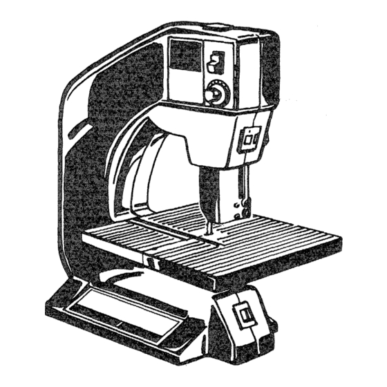
- Page 1 OWNERS MANUAL MODEL NO, 244288 CAUTION: Read Rules for ii i, Safe Operation ® and Instructions 10" BAND SAW Carefully Introduction Operation Maintenance Repair Parts SOLD BY SEARS, ROEBUCK AND CO., Chicago, IL 60684 U.S.A. PART SP4998 PRINTED IN U.S.A.
- Page 2 CENTER THOUGHOUT THE UNITED STATES. If this CRAFTSMAN 10" BAND SAW fails due to a defect in material or workrnanshtp within one year from date of This warranty gives you specific legal rights and you may also have other rights which vary from state to state.
- Page 3 BAND SAW SAFETY RULES For your own safety, do not attempt When cutting a large piece of material, make sure to operate your band saw until it is it is supported at table height. completely assembled and installed according to the ®...
- Page 4 DOUBLE INSULATED TOOLS WITH TWO-PRONG PLUGS Your SEARS _ooi is equipped with a two wire cord a dielectric material. This helps protect you in case of prong plug which can beUsedin standard failure of the standard functional insulation within Volt A_C, outlets: the electrical system.
- Page 5 UNPACKI G CONTENTS The Craftsman model 113.244200 Band Saw is shipped complete in one carton. Separate all parts from packing materials and check each one with the illustration and the list of Loose Parts to make certain all items are accounted...
- Page 6 GETTING TO KNOW YOUR BAND ON/OFF GUIDE SWITCH LOCK KNOB TRACKING ADJUSTMENT KNOB VARIABL D CONTROL HOUSING COVER LATCH UPPER TH RUST ROLLER ADJUSTMENT BLADE UPPER BLADE GUIDES TABLE COVER COVER RELEASE RELEASE BUTTON BUTTON EXTENSION MITER GAUGE LOWER TILT SCALE TABLE LOCK...
- Page 7 ON-OFF SWITCH . . . The On-Off Switch ha., miter gauge extension allows you to lower the blade guard within 1/8" of the material to be red locking lever which is included on switc THISFEATURE tS INTENDED TO PREVE# without interference from the blade...
- Page 8 _Find a Thrusz Roller among loose parts and insert 2. Find a Thrust Roller among loose parts and insert' in upper guide assembly. in lower guide assembly. LOWER BLADE GUIDES UPPER _BLADEGUIDES GUIDE I I_ PHILLIPS "_ SCREWS _ PHILLIPS THRUST ROLLER SCREWS...
- Page 9 PREPARING THE TABLE SCREWS SLOTT Loosen the guide bar lock knob, and lower the blade SCR EW guide assembly. TABLE Attach the blade guard on the upper guide assembly iNSERT TABLE and secure it with two screws. Locate the table insert and place it in the opening in the table.
- Page 10 Clean them When cutting very small pieces, use a stick to with Craftsman Gum and Pitch Remover. push the wood into the blade. The cord and the tool should be wiped with a dry...
- Page 11 ACCESSORIES NUMBER DESCRBPTION 9-26641 62" x 1/4" Blade 6 teeth solid wood )er inch - regular tooth 9-26642 62" x 3/8" Blade 6 teeth )er inch - regular tooth solid wood 9-26645 3er inch 62" x 1/8" Blade 15 teeth finishing 9-26646 62"...
- Page 12 ADJUSTMENTS F'" BLADE GUIDE ADJUSTING LOWER BLADE GUIDES BLADE 1. Loosen the two phittips screws that lock lower blade guides press the guides evenly against the sides of the blade but do not pinch sCREW blade. Release the guides and rotate upper wheel slightly clockwise...
- Page 13 BLADE ADJUSTINGUPPERBLADE GUADES 1. Loosenthe two phillips screws that lockthe upper blade guidesand pressthe two guidesevenly against t he sides of the bladebut donot pinchthe BLADE blade. Release t he guidesand rotate WHEEL(2) GUIDE slightlyCLOCKWISE movingthe blade downward. PHi LLIPS Makesureone guideis not farther awayfrom the SCREW bladethan the other andsecurelytigLlten phillips...
- Page 14 PART PART PART NAME PART NAME 328539 V.S. CONTROL 341452 HOUSING COVER SET 328705 TERMINAL 60301 SNAP RING (3) 328768 KNOB w/STUD 43038 WASHER (3) 340179 SCR EW 328522 IDLER WHEEL ASSEMBLY 328754 KNOB w/STUD 326291 WHEEL (2) 328773 SPAC ER 27399 BEARING 328538...
- Page 15 ----'x < < Page 15...
- Page 16 ® 10" BAND SAW OWNERS MANUAL SERVICE Model Number will be found on a plate attach- ed to the motor housing. Always mention Model Number when requesting service repair parts BAND your MODEL NO. parts listed ordered from Sears 113.244200 Service Center most...


