Advertisement
Quick Links
RCU50U and RCU50.2U
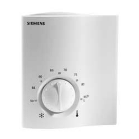
Room Temperature Controllers for
CAV Systems
Description
Features
Application
Product Numbers
RCU50U
The RCU microprocessor controlled CAV room controller is designed for air only, or air
and water heating and/or cooling systems. Controllers have proportional response.
• Modulating P-control
• 0 to 10 Vdc output for heating or cooling
• Automatic heating/cooling changeover (RCU50U)
• Manual heating/cooling changeover (RCU50.2U)
• Operating modes: Normal, Energy Saving, Frost Protection and Standby (RCU50U)
• Operating modes: Normal and OFF (RCU50.2U)
• Active 0 to 10 Vdc input for set point shifting (RCU50U)
• Operating mode changeover input for remote control (RCU50U)
• Adjustable minimum limitation for cooling output (RCU50U)
• Operating voltage 24 Vac
Controlling individual room temperature in HVAC installations that are heated or cooled.
Controlling these types of equipment:
• Valve actuators
• Air damper actuators
Product Numbers
RCU50U
RCU50.2U
NOTE:
To order without logo, change suffix to "/U/NL". Example: RCU50/U/NL.
Technical Instructions
Document No. 155-327P25
Table 1.
Features
Without operating mode selector
With manual heating/cooling changeover switch
Rev. 1, March, 2002
RCU50.2U
Siemens Building Technologies, Inc.
Advertisement

Summary of Contents for Siemens RCU50U
- Page 1 • Operating modes: Normal, Energy Saving, Frost Protection and Standby (RCU50U) • Operating modes: Normal and OFF (RCU50.2U) • Active 0 to 10 Vdc input for set point shifting (RCU50U) • Operating mode changeover input for remote control (RCU50U) • Adjustable minimum limitation for cooling output (RCU50U) •...
- Page 2 0 to10 Vdc control commands. The RCU50U and RCU50.2U provide P-control. With the RCU50U, the proportional band can be 2°F or 7°F (1°C or 4°C) in heating mode and 1°F or 3.5°F (0.5°C or 2°C) in cooling mode (selectable with DIP Switch No.
- Page 3 RCU50U and RCU50.2U Room Temperature Controllers Technical Instructions For VAV Systems Document Number 155-327P25 Rev. 1, March, 2002 Minimum Limitation of Cooling Signal, Continued Figure 3. Potentiometer Location (RCU50U). Inversion of Output With the RCU50.2U, the output signal can be inverted with the help of DIP Switch Signal No.
-
Page 4: Operating Modes
Technical Instructions RCU50U and RCU50.2U Room Temperature Controllers Document Number 155-327P25 for CAV Systems Rev. 1, March, 2002 Set Point Limit Stops The room temperature set point can be limited in increments of 2°F (1°C) by using the minimum and maximum set point limit stops. This prevents arbitrary set point readjustments. - Page 5 RCU50U and RCU50.2U Room Temperature Controllers Technical Instructions For VAV Systems Document Number 155-327P25 Rev. 1, March, 2002 Mechanical Design, The screw terminals are mounted on the base. The DIP switches and the potentiometer Continued are located at the rear of the unit. To access the DIP switches, remove the controller from the controller base.
- Page 6 • Check the settings of DIP Switches No. 1 through No. 5 and of the potentiometer of Notes, Continued the RCU50U, and of DIP Switch No. 1 of the RCU50.2U and change them, if required • After applying power, the controller makes a reset, which takes about three seconds;...
- Page 7 RCU50U and RCU50.2U Room Temperature Controllers Technical Instructions For VAV Systems Document Number 155-327P25 Rev. 1, March, 2002 Drywall Mounting, 4. Using the controller base as a template, mark the hole locations with a pencil. Continued 5. Drill two 1/4-inch diameter holes for plastic wall anchors.
- Page 8 Rev. 1, March, 2002 4 × 4-inch Electrical Wall An ARG70 wall plate adapter is required to mount an RCU50U or RCU50.2U controller Box Mounting to a 4 × 4-inch electrical wall box. The ARG70 wall plate adapter is included with electrical wall box mount models.
- Page 9 Rev. 1, March, 2002 2 × 4-inch Electrical Wall An ARG70 wall plate adapter is required to mount an RCU50U or RCU50.2U controller Box Mounting to a 2 × 4-inch electrical wall box. The ARG70 wall plate adapter is included with electrical wall box mount models.
-
Page 10: Specifications
Signal input terminals 2 and 3 for changeover QAH11.1 safety class 2 sensor NTC resistor 3K Ω @ 77°F (25°C) Maximum copper cable length 16 AWG For Input Signal terminals 1 & 2 (RCU50U) 262 feet (80m) For Input Signal D1 (RCU50U) 262 feet (80m) Operation Environmental Temperature 32°F to 122°F (0°C to 50°C) -
Page 11: Wiring Diagrams
RCU50U and RCU50.2U Room Temperature Controllers Technical Instructions For VAV Systems Document Number 155-327P25 Rev. 1, March, 2002 Wiring Diagrams D1 GND max. max. Figure 14. RCU50U Wiring Diagram. Figure 15. RCU50.2U Wiring Diagram. Signal input set point shift Operating voltage, 24 Vac positive...


