Sign In
Upload
Manuals
Brands
ABB Manuals
Circuit breakers
E2S 20
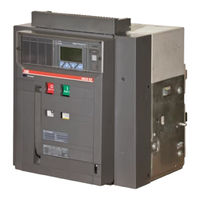
ABB E2S 20 Voltage Circuit Breaker Manuals
Manuals and User Guides for ABB E2S 20 Voltage Circuit Breaker. We have
1
ABB E2S 20 Voltage Circuit Breaker manual available for free PDF download: Installation, Service And Maintenance Instructions
ABB E2S 20 Installation, Service And Maintenance Instructions (162 pages)
Low voltage air circuit-breakers
Brand:
ABB
| Category:
Circuit breakers
| Size: 5 MB
Table of Contents
Index
2
Description
7
General Characteristics
7
External Front View of the Circuit-Breaker
7
Moving Part Construction Characteristics
7
Storage, Lifting and Weights
8
Checking on Receipt
8
Fixed Part Construction Characteristics
8
Installation
9
Installation Room
9
Table of the Circuit-Breaker Weights (Kg.)
9
Installation of the Fixed Part of the Withdrawable Circuit-Breaker
9
Installation of the Fixed Part
10
Installation of the Fixed Part on Board a Ship
10
Example for E1B 08 According to the Nameplate Diagram
10
Electrical Connections
11
Installation of the Flange on the Compartment Door
11
Connections to the Power Circuit
11
Shapes of the Terminals
11
Assembly Procedure for the Connection Busbars
13
Earthing
13
Wiring the Circuit-Breaker Auxiliary Circuits
13
Interfacing Elements for Fixed Circuit-Breakers
13
Withdrawable Circuit-Breaker
14
10 Contacts in Position
14
5 Contacts in Position
14
Conversion of the Auxiliary Contacts or of the Signalling Contacts
15
Auxiliary Contacts
15
Signalling Contacts Disconnected
15
Putting into Service
16
General Procedures
16
Instructions for Use
17
Operating and Signalling Parts
17
Circuit-Breaker Closing and Opening Procedures
18
Electrical Loading of the Closing Springs
18
Closing the Circuit-Breaker
18
Opening the Circuit-Breaker
18
Racking-In/Out Operation
19
Positioning the Moving Part in the Fixed Part
19
Maintenance
20
Warning
20
Maintenance Program
21
Maintenance Operations
21
Preliminary Operations
21
General Inspection of the Circuit-Breaker
22
Checking Contact Wear
22
Operating Mechanism Maintenance
23
Measures to be Taken for any Operating Anomalies
24
Accessories
25
Electrical Accessories
25
Undervoltage Release (YU)
25
Time Delay Device for Undervoltage Release (D)
26
Geared Motor for Automatic Closing Spring Loading (M)
26
Mechanical and Electrical Trip Signalling for Overcurrent Releases
27
Transformers and Operation Counters
27
Mechanical Trip Signalling for Overcurrent Releases
27
Coil for Resetting the Mechanical Release Trip Indicator
27
Auxiliary Contacts
27
Mechanical Locks
28
Transparent Protection Covers
28
Interlock between Circuit-Breakers
28
Homopolar Toroid for Residual Current Protection
28
Mechanical Operations Counter
28
Spare Parts
29
Retrofitting Kits
29
Protection Releases - General Notes
30
Safety Notes
31
Notes for Dielectric Stiffness Tests
31
Abbreviations and Notes
31
SACE PR121/P Release - Identification
32
Standard
32
Specifications
32
Electrical Characteristics
32
Environmental Characteristics
33
Communication Bus
33
Protection Functions
33
Calculating the RMS
33
Description of the Protection Functions
34
Thermal Memory “L”
34
Protection “L”
34
Protection “S”
34
Summary Table of Protections
35
Table of Measurements
35
Trip Curves
36
Trip Curves for Functions L-I
36
Trip Curves for Functions L-S
36
Trip Curves for Functions L-S(T=K)-I
37
Trip Curves for Function G
37
Other Functions
38
Connections
38
CS and TC Connection Check
38
Current Sensor Connection for External Neutral
38
Trip Test
39
Initial Settings
39
Changing Protection Functions
39
Example of Settings
39
Operating Instructions / Operation in Service
40
Neutral Adjustment
40
Neutral Adjustment Specifications
40
Replacing an Electronic Release
40
Definition of the Alarms and Signals for the PR121/P Unit
41
Optical Signals
41
Troubleshooting
42
In the Case of a Fault
42
BT030 Communication Unit
42
PR021/K and HMI030 Units
42
SACE PR122/P Release - Identification
43
Self-Supply
44
Auxiliary Power Supply
44
Powered by the PR120/V Module
44
Description of Inputs/Outputs
44
Mains Frequency
45
Harmonic Distortion
45
Circuit-Breaker State
45
Measurement Functions
45
Thermal Memory “S”
46
Start-Up Threshold “S”
46
Zone Selectivity “S”
47
Protection “I”
47
Start-Up Threshold “I”
47
Protection “G”
47
Start-Up Threshold “G”
48
Zone Selectivity “G”
48
Protection against Phase Unbalance “U”
48
Protection against Overtemperature Inside the Relay “OT”
48
Load Control Function
49
Protection “UV”
49
Protection “OV”
49
Protection “RV”
49
Summary Table of the Protection Function Settings for the PR122/P
50
CS and TC Connection Test
58
User Interface
60
Description of the Icons Displayed
60
Use of Pushbuttons
60
Read and Edit Modes
61
Changing Parameters
61
Default Settings
64
Protections Menu
66
Protections Menu Table
66
Measurements Menu
69
Measurements Menu Table
69
Settings Menu
69
Settings Menu Table
69
PR120/D-M - COM Module
71
PR120/D WL-COM Module
71
Information Menu
72
Information on the Trip and Opening Data
72
Definition of Alarms and Signals in the PR122/P Unit
72
Electrical Signals
72
Table of Error and Warning Messages
73
Alarm Message
73
Error Messages Displayed in Pop-Up Windows
74
Troubleshooting PR122/P Unit
75
ABB SACE PR010/T Test and Configuration Unit
76
SACE PR123/P Release - Identification
77
Specifications
77
Rms Calculation
79
Trip Curves for Function L in Accordance with IEC 60255-3 (Type B)
91
Trip Curves for Function L in Accordance with IEC 60255-3 (Type C)
91
Trip Curves for Function D
92
Trip Curves for Function U
92
Trip Curves for Function UV
93
Trip Curves for Function OV
93
Trip Curves for Function RV
94
Trip Curves for Function RP
94
Protections Menu
103
Modules
114
PR120/V - MEASURING Module
114
Table of Submenus for the PR120/V Module
117
Historicals
118
Trips
118
Events
118
Measurements
118
Energy
119
Peak Factor
119
Waveforms
119
Electrical Characteristics of the Transformers
120
Mechanical Characteristics
120
Operating Frequency Range
120
PR120/D-M - COM Communication Module
121
Front View
121
Releases Complete with the Module
121
Communication Functions Available
121
PR120/K Signalling Module
122
Characteristics of the Digital Input
122
Characteristics of the Signalling Contacts
122
Power Supply
123
PR120/K Module Menu
123
Configurable Input
123
Input Configuration Settings
123
PR120/K Module Menu Layout
124
PR120/D-BT - WL-COM Wireless Communication Module
125
PR021/K Outside Signalling Unit
126
General Characteristics of the Signalling Relays
126
Relay Functions
126
PR021/K Signalling Unit Menu
126
PR021/K Unit Menu Table
127
SD-Pocket
128
SD-Testbus2
128
Data Logger (Recorder)
129
Description of the Data Logger Menu
129
Enabling the Data Logger
129
Setting the Sampling Frequency
129
Setting and Viewing Customized Stop Events (Triggers)
130
Setting the Stopping Delay
130
Restart/Stop Data Logger
130
Recording Time Windows
130
Description of the Information Given by the Data Logger System
131
Access to Saved Data from the System
131
Data Logger Commands from the System
132
Example of Data Logger Operation
132
Table Showing List of Events
133
Combining the Devices Needed to Customize Settings
133
Residual Current Protection Function
134
Rc Test Menu
135
Overall Dimensions
136
Fixed Circuit-Breaker
136
Fixed Circuit-Breaker
137
Withdrawable Circuit-Breaker
143
Circuit Diagrams
150
Operating Status Shown
150
Versions
150
Incompatibilities
151
Description of Figures
151
Circuit Diagram Symbols
153
Circuit Diagram - Operating Status
154
Auxiliary Circuits of the PR121, PR122 and PR123 Releases
157
PR120/D-M Communication Module
158
PR021/K Signalling Unit
159
Advertisement
Advertisement
Related Products
ABB E2S 08
ABB E2S 10
ABB E2S 16
ABB E2S 12
ABB E2N 16
ABB E2N 12
ABB E2B 20
ABB E2L 16
ABB SACE Emax E2.2-A
ABB E2L 12
ABB Categories
Industrial Equipment
Controller
Measuring Instruments
Battery Charger
DC Drives
More ABB Manuals
Login
Sign In
OR
Sign in with Facebook
Sign in with Google
Upload manual
Upload from disk
Upload from URL