Sign In
Upload
Manuals
Brands
Bosch Manuals
Controller
ME 200
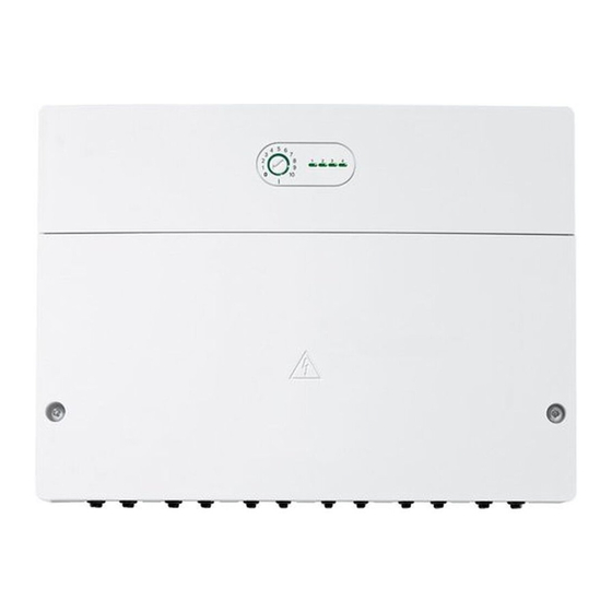
Bosch ME 200 Manuals
Manuals and User Guides for Bosch ME 200. We have
1
Bosch ME 200 manual available for free PDF download: Installation Instructions For Contractors
Bosch ME 200 Installation Instructions For Contractors (100 pages)
Brand:
Bosch
| Category:
Controller
| Size: 10.68 MB
Table of Contents
Deutsch
2
1 Symbolerklärung und Sicherheitshinweise
2
Table of Contents
2
Allgemeine Sicherheitshinweise
2
Symbolerklärung
2
2 Angaben zum Produkt
3
Systemvoraussetzung
3
Wichtige Hinweise zur Verwendung
4
Funktionsbeschreibung
4
Kodierschalter Einstellen
4
Lieferumfang
4
Technische Daten
4
Ergänzendes Zubehör
5
Reinigung
5
3 Installation
5
Installation der Temperaturfühler am Pufferspeicher
5
Elektrischer Anschluss
5
Anschluss BUS-Verbindung und Temperaturfühler (Kleinspannungsseite)
5
Anschluss Spannungsversorgung, Pumpe und Mischer (Netzspannungsseite 230V)
6
Anschlusspläne mit Anlagenbeispielen
6
Überblick Anschlussklemmenbelegung
7
Kodierschalter Einstellen
8
Inbetriebnahme der Anlage und des Moduls
8
Weitere Zustandsanzeigen am Modul
8
Menü Einstellungen Alternativer Wärmeerzeuger
8
Menü Diagnose
10
5 Störungen Beheben
10
Betriebsanzeige des Moduls (Integriert IM Kodierschalter)
10
Betriebsanzeige "1": Alternativer Wärmeerzeuger
11
Betriebsanzeige "2": Wärmeerzeuger-Bypassventil/Pumpe Heizkreis 1 (Autark)
11
Betriebsanzeige "3": Pufferspeicher
11
Betriebsanzeige "4": Sperre des Konventionellen Wärmeerzeugers
11
Störungen ohne Anzeige am Modul
11
6 Übersicht des Servicemenüs
12
7 Umweltschutz/Entsorgung
12
Čeština
13
1 Vysvětlení Symbolů a Bezpečnostní Pokyny
13
Použité Symboly
13
Všeobecné Bezpečnostní Pokyny
13
2 Údaje O Výrobku
14
Systémový Předpoklad
14
Důležité Poznámky K PoužíVání
15
Popis Funkce
15
Nastavení Kódovacího Spínače
15
Rozsah Dodávky
15
Technické Údaje
15
Doplňkové Příslušenství
16
ČIštění
16
3 Instalace
16
Instalace Čidel Teploty Na Akumulační NádržI
16
Elektrické Připojení
16
Připojení Sběrnicového Spojení a Čidla Teploty (Strana Malého Napětí)
16
Připojení Napájení Čerpadla a Směšovače (Strana Síťového Napájení 230 V) ElektrickýM Proudem
17
Elektrická Schémata Zapojení S Příklady Zapojení Topného Systému
17
Přehled Osazení Připojovacích Svorek
18
4 Uvedení Do Provozu
19
Další Stavové Indikátory Na Modulu
19
Nabídka Nastavení Alternativních Zdrojů Tepla
19
Nastavení Kódovacího Spínače
19
Uvedení Systému a Modulu Do Provozu
19
Menu Diagnostika
21
5 Odstraňování Poruch
21
Zobrazení Provozního Stavu Modulu (Integrován V KódovacíM SpínačI)
21
Zobrazení Provozního Stavu "1": Alternativní Zdroj Tepla
22
Zobrazení Provozního Stavu "2": Ventil Obtoku Zdroje Tepla / Otopný Okruh Čerpadla 1 (Autarkní)
22
Zobrazení Provozního Stavu "3": Akumulační Nádrž
22
Zobrazení Provozního Stavu "4": Blokování Konvenčního Zdroje Tepla
22
Poruchy Bez Zobrazení Na Modulu
22
6 Přehled Servisního Menu
23
7 Ochrana Životního Prostředí a Likvidace Odpadu
23
English
24
1 Explanation of Symbols and Safety Instructions
24
Explanation of Symbols
24
General Safety Instructions
24
2 Product Information
25
System Requirements
25
Important Notices on Use
26
Function Definition
26
Setting the Coding Switch
26
Scope of Delivery
26
Specification
26
Additional Accessories
27
Cleaning
27
3 Installation
27
Installation of the Temperature Sensor at the Buffer Cylinder
27
Electrical Connection
27
Establishing the BUS Connection and Temperature Sensor (Extra-Low Voltage Side)
27
Connecting the Power Supply, Pump and Mixer (Mains Voltage Side 230 V)
28
Connection Diagrams with System Schematics
28
Overview of the Terminal Assignment
29
Setting the Coding Switch
30
Commissioning of the System and Module
30
More Status Indicators at the Module
30
Settings Menu of Alternative Heat Source
30
Diagnosis Menu
32
5 Troubleshooting
32
Status Indicator of the Module (Integrated in the Coding Switch)
32
Status Indicator "1": Alternative Heat Source
32
Status Indicator "2": Heat Source Bypass Valve/Pump for Heating Circuit 1 (Stand-Alone)
33
Status Indicator "3": Buffer Cylinder
33
Status Indicator "4": Conventional Heat Source Block
33
Faults Not Indicated at the Module
33
6 Overview of the Service Menu
33
7 Environmental Protection/Disposal
34
Français
35
1 Explication des Symboles Et Mesures de Sécurité
35
Explications des Symboles
35
Consignes Générales de Sécurité
35
2 Informations Sur Le Produit
36
Conditions du Système
36
Consignes D'utilisation Importantes Relatives À L'utilisation
37
Fonctionnement
37
Réglage de L'interrupteur Codé
37
Contenu de Livraison
37
Caractéristiques Techniques
37
Accessoires Complémentaires
38
Nettoyage
38
3 Installation
38
Installation des Sondes de Température Sur Le Ballon Tampon
38
Raccordement Électrique
39
Raccordement Liaison BUS Et Sonde de Température (Côté Basse Tension)
39
Raccordement de L'alimentation Électrique, de la Pompe Et de la Vanne de Mélange (Côté Tension de Réseau 230 V)
39
Schémas de Connexion Avec Exemples D'installation
40
Vue D'ensemble Affectation des Bornes de Raccordement
41
Réglage de L'interrupteur Codé
42
Mise en Service du Module Et de L'installation
42
Autres Affichages D'état Sur Le Module
42
Menu Réglages Générateurs de Chaleur Alternatifs
42
Menu Diagnostic
44
5 Eliminer Les Défauts
44
Témoin de Fonctionnement du Module (Intégré Sur L'interrupteur Codé)
45
Témoin de Fonctionnement " 1 " : Générateur de Chaleur Alternatif
45
Témoin de Fonctionnement " 2 " : Générateur de
45
Témoin de Fonctionnement " 3 " : Ballon Tampon
46
Témoin de Fonctionnement " 4 " : Verrouillage du Générateur de Chaleur Traditionnel
46
Défauts Sans Affichage Sur Le Module
46
6 Aperçu des Menus de Service
46
7 Protection de L'environnement/Recyclage
47
Dutch
48
1 Toelichting Bij de Symbolen en Veiligheidsinstructies
48
Symboolverklaringen
48
Algemene Veiligheidsvoorschriften
48
2 Gegevens Betreffende Het Product
49
Systeemvoorwaarde
49
Belangrijke Adviezen Voor Het Gebruik
50
Functiebeschrijving
50
Codeerschakelaar Instellen
50
Leveringsomvang
50
Technische Gegevens
50
Aanvullend Toebehoren
51
Reiniging
51
3 Installatie
51
Installatie Van de Temperatuursensor Op Buffervat
51
Elektrische Aansluiting
51
Aansluiting BUS-Verbinding en Temperatuursensor (Laagspanningszijde)
51
Aansluiting Voedingsspanning Pomp en Mengkraan (Netspanningszijde 230 V)
52
Aansluitschema's Met Installatievoorbeelden
52
Overzicht Bezetting Aansluitklemmen
53
Codeerschakelaar Instellen
54
Inbedrijfstelling Van de Installatie en de Module
54
Overige Toestandsindicaties Op Module
54
Menu Instellingen Alternatieve Warmteproducent
54
Menu Diagnose
56
5 Storingen Verhelpen
56
Bedrijfsindicatie Van de Module (Geïntegreerd in de Codeerschakelaar)
56
Bedrijfsindicatie "1": Alternatieve Warmteproducent
57
Bedrijfsindicatie "2": Bypass-Ventiel Warmteproducent/Pomp CV-Circuit 1 (Autonoom)
57
Bedrijfsindicatie "3": Buffervat
57
Bedrijfsindicatie "4": Blokkade Van de Conventionele Warmteproducent
57
Storingen Zonder Weergave Op Module
57
6 Overzicht Van de Servicemenu's
58
7 Milieubescherming/Afvalverwerking
58
Italiano
59
1 Significato Dei Simboli E Avvertenze DI Sicurezza
59
Significato Dei Simboli
59
Avvertenze DI Sicurezza Generali
59
2 Descrizione del Prodotto
60
Requisiti DI Sistema
60
Indicazioni Importanti Sull'utilizzo
61
Descrizione del Funzionamento
61
Impostazione del Selettore DI Codifica
61
Volume DI Fornitura
61
Dati Tecnici
61
Accessori Complementari
62
Pulizia
62
3 Installazione
62
Installazione Della Sonda DI Temperatura Sull'accumulatore Inerziale
62
Collegamento Elettrico
63
Collegamenti del Sistema BUS E Delle Sonde DI Temperatura (Lato Bassa Tensione)
63
Collegamento Alla Tensione DI Alimentazione Elettrica Per Circolatore E Valvola Miscelatrice (Lato Tensione DI Rete 230 V)
63
Schemi Elettrici DI Collegamento con Esempi DI
64
Impianti
64
Panoramica Sull'occupazione Dei Morsetti DI Collegamento
65
Impostazione del Selettore DI Codifica
66
Messa in Funzione Dell'impianto E del Modulo
66
Altri Indicatori DI Stato Sul Modulo
66
Menu Impostazioni Generatore DI Calore Alternativo
66
Menu Diagnosi
68
5 Eliminazione Delle Disfunzioni
68
Indicatore DI Funzionamento del Modulo (Integrato Nel Selettore DI Codifica)
69
Indicatore DI Funzionamento "1": Generatore DI Calore Alternativo
69
Indicatore DI Funzionamento "2": Valvola Bypass/ Circolatore Circuito DI Riscaldamento del Generatore DI Calore 1 (Autonomo)
69
Indicatore DI Funzionamento "3": Accumulatore
70
Inerziale
70
Indicatore DI Funzionamento "4": Generatore DI Calore a Condensazione Disabilitato
70
Disfunzioni Senza Visualizzazione Sul Modulo
70
6 Panoramica del Menu DI Servizio (Manutenzione)
70
7 Protezione Dell'ambiente/Smaltimento
71
Polski
72
Objaśnienie Symboli I Wskazówki Dotyczące Bezpieczeństwa
72
Objaśnienie Symboli
72
Ogólne Zalecenia Bezpieczeństwa
73
2 Informacje O Produkcie
74
Wymagania Systemowe
74
Ważne Wskazówki Dotyczące Zastosowania
74
Opis Działania
74
Ustawianie Przełącznika Kodującego
75
Zakres Dostawy
75
Dane Techniczne
75
Osprzęt Uzupełniający
75
Czyszczenie
75
3 Instalacja
76
Instalacja Czujników Temperatury Na Zasobniku Buforowym
76
Podłączenie Elektryczne
76
Podłączenie Połączenia Magistrali BUS I Czujnika Temperatury (Strona Napięcia Bardzo Niskiego)
76
Przyłącze Napięcia Zasilającego, Pompy I Zaworu Mieszającego (Strona Napięcia Sieciowego 230 V)
77
Schematy Połączeń Z Przykładami Instalacji
77
Schemat Przyporządkowania Zacisków Przyłączeniowych
78
Ustawianie Przełącznika Kodującego
79
Uruchomienie Instalacji I Modułu
79
Pozostałe Wskazania Stanu Na Module
79
Menu Ustawień Alternatywnego Urządzenia Grzewczego
79
Menu Diagnoza
81
5 Usuwanie Usterek
81
Wskaźnik Stanu Pracy Modułu (Wbudowany W Przełącznik Kodujący)
81
Wskaźnik Stanu Pracy "1": Alternatywne Urządzenie Grzewcze
82
Wskaźnik Stanu Pracy "2": Zawór Obejściowy/Pompa Obiegu Grzewczego 1 (Autarkiczna)
82
Wskaźnik Stanu Pracy "3": Zasobnik Buforowy
82
Wskaźnik Stanu Pracy "4": Blokada Konwencjonalnego Urządzenia Grzewczego
82
Usterki Bez Wskazania Na Module
82
6 PrzegląD Menu Serwisowego
83
7 Ochrona Środowiska/Utylizacja
83
Advertisement
Advertisement
Related Products
Bosch MPC-8000-C
Bosch Access Modular Controller 2
Bosch Rexroth IndraDrive MPH-02
Bosch Rexroth IndraDrive MPB-02
Bosch Rexroth IndraDrive MPD-02
Bosch MS 200
Bosch MPC-C Series
Bosch Mini Remote
Bosch Mini Remote Dropbar
Bosch MES4000/01
Bosch Categories
Dishwasher
Washer
Oven
Power Tool
Dryer
More Bosch Manuals
Login
Sign In
OR
Sign in with Facebook
Sign in with Google
Upload manual
Upload from disk
Upload from URL