Sign In
Upload
Manuals
Brands
Canon Manuals
Camcorder
DC10 E
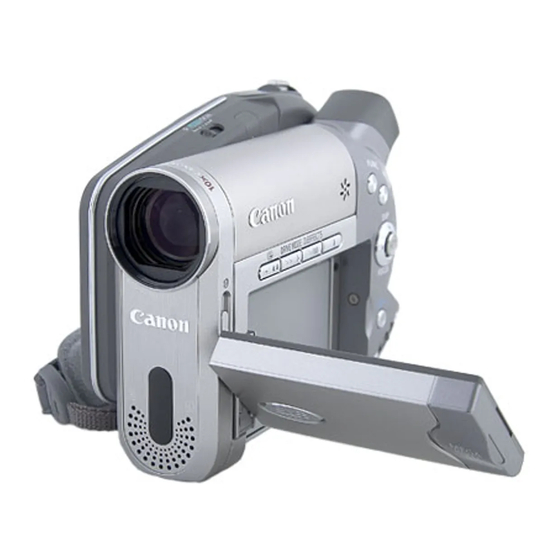
Canon DC10 E Manuals
Manuals and User Guides for Canon DC10 E. We have
1
Canon DC10 E manual available for free PDF download: Service Manual
Canon DC10 E Service Manual (206 pages)
Digital Video Camera
Brand:
Canon
| Category:
Camcorder
| Size: 16.43 MB
Table of Contents
English
2
Table of Contents
2
1 Product Overview
3
Development Concept
3
List of Main Features
4
High Image Quality
4
Advanced Functions and Comfortable Operation
4
Product Specifications Comparison Chart
9
Function and Performance List
10
2 Technical Explanation
15
Design Concept
15
TS Mech
17
Overview of TS Mech
17
Main Mechanical Parts
18
3 Performance
19
4 System Diagram (Common to All Models)
37
PCB Functions
39
Power Supply Circuit
41
Startup of Power Supply
41
Power Fuses
43
Power Supply Circuits
44
Built-In Charger Circuit
45
Outline
46
Operation at Charging
46
Conditions to Start Charging
46
Progress of Charging
47
Signal Processing Circuit
48
Outline of Signal Processing Circuit
48
DC10 E Outline of Signal Processing Circuit
48
DC10 E Outline of Signal Processing Circuit
49
Camera/Card Signal Processing (DC10 E)
50
Camera Motion Picture Recording
50
Card Still Picture Recording
50
Camera/Card Signal Processing (DC20 E)
52
2-Megapixel Camera System
52
Camera Motion Picture Recording
52
Card Still Picture Recording
53
Recorder Signal Processing
54
Audio Signal Flow
55
System Control
56
Outline of System Control
56
Major Functions of each MI-COM
57
Personal Computer Connection Mode (USB)
58
Disk Functions
59
Playlist Editing Functions
59
Still Image Shooting and Direct Print
60
Disassembling and Reassembling
62
Notes
62
Safety Precautions
62
List of Supplies
63
Disassembling / Reassembling Flowchart
64
Separation of R Upper Cover
65
Separation of R-LCD Unit
67
Separation of Front Cover Unit
69
Separation of Rear Cover Unit
71
Separation of Flash PCB ASS'Y (DC20 E Only)
73
Separation of CVF Unit, SUB PCB
75
Separation of GYRO PCB
76
Separation of Camera Unit
77
Separation of Center Cover
78
Separation of Zoom Ass'y, CARD PCB
80
Separation of MAIN PCB
81
Separation of TS Mech Section
83
Separation of Main Frame
84
Disassembly of Front Cover Unit
87
Disassembly of Front Cover Unit
89
Disassembly of L Cover Unit
93
Disassembly of Lock Ass'y
95
Separation of LCD Ass'y
98
Disassembly of LCD Unit
100
Disassembly of LCD Hinge Ass'y
103
Disassembly of CVF Unit
104
Disassembly of Rear Cover Unit
108
Disassembly of Rear Cover Unit
112
Disassembly of Camera Unit
113
Disassembly of Lens Unit
115
List of Screws Used
117
List of Disassembly Photos
118
Maintenance Tools
122
List of Maintenance Tools
122
Setting
123
Using the Extension Connector
123
Service Modes
124
Outline
124
How to Change over to Service Mode
124
How to Operate Wireless Remote Controller in Service Mode
125
Indication in Service Mode
126
Service Mode Transition Card (DY9-1406-000)
127
Description of Service Modes
128
Error Rate
128
Commands Particular to Camera
129
Checking the Lens Resetting
130
Functional Check of Control Keys and Switches
131
CCM MI-COM Input Port
131
CCM MI-COM A/D Port
131
SUB MI-COM Input Port
131
SUB MI-COM A/D Port
131
BACK END MI-COM Input Port
132
Adjustment Procedures
133
Adjustment Items in Part Replacement
133
CCD Section (1) - CCD Image Adjustment - (DC20 E Only)
135
Internal Camera Temperature Check (1)
135
Iris Adjustment (Coarse Adjustment)
137
Preparation for CCD Image Adjustment (1)
138
Preparation for CCD Image Adjustment (2)
139
Internal Camera Temperature Check (2)
140
CCD Image Adjustment (Low Temperature)
141
CCD Image Adjustment Result Check (Low Temperature)
142
AF Section Adjustment
143
VCM Adjustment
144
CZ Automatic Adjustment
145
Cam Correction (AUTO)
145
IS Section Adjustment
146
Gyro Offset Adjustment
146
Data Writing
147
CCD Section (2) (DC20 E Only)
148
Internal Camera Temperature Check (3)
148
CCD Image Adjustment (High Temperature)
149
CCD Image Adjustment Result Check
150
Camera Section Adjustment
152
Iris Adjustment
152
WB Adjustment (1)
153
Color Balance Adjustment
153
Data Writing
154
CCD Pixel Missing Compensation
155
Recorder Section Adjustment
157
Playback Error Rate Check
157
Self-Recording Error Rate Check
158
LCD PCB Setting Destination
158
CVF Adjustment
159
Forced CVF ON, Adjustment Image (B/W) Setting
159
CVF Frequency Adjustment
159
COM-DC Level Adjustment
160
COM Amplitude Adjustment
161
Brightness Adjustment
162
Contrast Adjustment
163
Release of Forced CVF on
164
Service Hints
166
Arrangement of Circuit Boards
166
Location of Main Elements
167
Main Pcb
168
Sub Pcb
169
Current Consumption Check
170
Troubleshooting
171
Power Supply Malfunction
171
Camera Picture Malfunction
172
Malfunction of Playback Picture
173
Flow Chart for Checking Malfunction of Playback Picture
173
Checking Method
174
Cautions on Handling TS Mech Unit
177
Periodic Checkup and Maintenance of TS Mech Unit
181
Cleaning of Pickup Lens
181
Cleaning Inside of CVF Unit
182
Disposing of the Lithium Battery
183
How to Remove the Built-In Lithium Battery When Discarding the Video Camera
183
Warning Displays
185
Unknown
190
Block Diagrams
190
Interconnection Diagram
192
Camera Section-1 (Dc10 A,Dc10 E,DM-Dc10 Only)
193
Camera Section-1 (Dc20 A,Dc20 E,DM-Dc20 Only)
194
Camera Section-2
195
Camera Section-3
196
Camera Section-4
197
Camera Section-5
198
Camera Section-6
199
System Control Section
200
Audio-Video Section
201
Power Supply Section
202
Flash Pcb Section (Dc20 A,Dc20 E,DM-Dc20 Only)
203
Lcd Pcb Section
204
Card/Li, DC Jack Pcb Section
205
Fpc Section
206
Advertisement
Advertisement
Related Products
Canon DC100 - WL Remote Control
Canon DC10 - TC Converter
Canon DC19
Canon DC20 E
Canon DC310
Canon DC420
Canon DC95
Canon DC201
Canon DC211
Canon DC 320
Canon Categories
Printer
Digital Camera
All in One Printer
Camcorder
Scanner
More Canon Manuals
Login
Sign In
OR
Sign in with Facebook
Sign in with Google
Upload manual
Upload from disk
Upload from URL