Sign In
Upload
Manuals
Brands
Cisco Manuals
Network Hardware
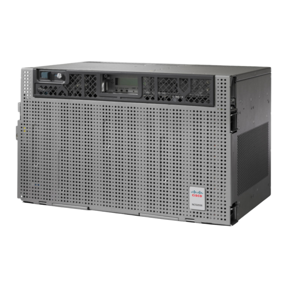
NCS 2006
Cisco NCS 2006 Manuals
Manuals and User Guides for Cisco NCS 2006. We have
1
Cisco NCS 2006 manual available for free PDF download: Hardware Installation Manual
Cisco NCS 2006 Hardware Installation Manual (510 pages)
ncs 2000 series
Brand:
Cisco
| Category:
Network Hardware
| Size: 24.61 MB
Table of Contents
Table of Contents
3
Revision History
17
Audience
18
Document Objectives
18
Document Organization
18
Related Documentation
20
Document Conventions
21
Obtaining Documentation, Obtaining Support, and Security Guidelines
27
Obtaining Optical Networking Information
27
Where to Find Safety and Warning Information
27
Overview
29
Compliance Standards
29
Cisco NCS 2002 Shelf
29
Chapter
29
Cisco NCS 2006 Shelf
31
Cisco NCS 2015 Shelf
32
Preparing to Install the Cisco NCS 2002, NCS 2006, and NCS 2015 Shelf
37
Important Safety Recommendations
37
Required Tools and Equipment
38
Cisco Supplied Materials
38
User Supplied Materials
41
Ordering Solutions for NCS 2002, NCS 2006, and NCS 2015
44
Card Slot Requirements
44
Ncs 2002
44
Ncs 2006
44
Ncs 2015
44
Ncs 2006
45
Ncs 2015
46
Card Replacement
47
NTP-L41 Unpacking and Inspecting the Shelf
48
DLP-L62 Unpacking and Verifying the Shelf
48
DLP-L63 Inspecting the Shelf
50
Chapter 3 Cisco NCS 2002 Installation Overview
51
Cisco NCS 2002 Installation Overview
51
Installing the Air Flow Regulator
53
Air Deflector
53
Air Plenum
54
Air Plenum Rack and Cabinet Compatibility
55
NTP-L42 Install the Air Plenum in NCS 2002 Shelf
56
DLP-L65 Installing Air Plenum for NCS 2002 Shelf in ANSI 19-Inch Configuration
58
DLP-L69 Installing Air Plenum in NCS 2002 Shelf for ANSI 23-Inch Configuration
61
DLP-L71 Installing Pre-Assembled Air Plenums in ANSI 23-Inch Configuration
66
DLP-L70 Installing Air Plenum for NCS 2002 Shelf in ETSI Configuration
68
Mounting the Cisco NCS 2002 Brackets
73
NTP-L44 Mounting the Brackets in ANSI Configuration
73
Configuration
74
DLP-L35 Mounting the 19-Inch Brackets on the NCS 2002 Shelf for ANSI Rack Configuration
74
Configuration
75
DLP-L36 Mounting the 23-Inch Brackets on the NCS 2002 Shelf for ANSI Rack Configuration
75
For ANSI Rack Configuration
77
NTP-L45 Mounting the Brackets in ETSI Configuration
79
DLP-L38 Mounting the Brackets on the NCS 2002 Shelf for ETSI Rack Configuration
80
Rack Configuration
82
For ETSI Rack Configuration
83
DLP-L41 Mounting the Bracket with Air Deflectors (Front-To-Top) on the NCS 2002 Shelf for ETSI Rack Configuration
86
Mounting the Cisco NCS 2002 Shelf
89
ANSI Rack Installation
89
Mounting a Single Node
90
ETSI Rack Installation
90
Mounting a Single Node
92
Wall Mounting the NCS 2002 Shelf
93
NTP-L42 Installing the NCS 2002 Shelf
93
Dlp-L42 Mounting the Ncs 2002 Shelf on a Rack (One Person)
95
Step 1
96
DLP-L42 Mounting the NCS 2002 Shelf on a Rack (One Person)
96
DLP-L43 Mounting the NCS 2002 Shelf on the Wall
97
DLP-L44 Mounting the NCS 2002 Shelf on the Desktop
100
Step 5
100
Connecting Power and Ground
103
Power and Ground Description
103
ANSI Power and Ground
103
ETSI Power and Ground
104
NTP-L35 Installing the Power and Ground to the NCS 2002 Shelf
104
Electrostatic Discharge and Grounding Guide for Cisco NCS
107
Step 1
107
DLP-L49 Connecting Office Power (AC) to the NCS 2002 Shelf
108
Stop. You Have Completed this Procedure
108
DLP-L50 Connecting Office Power (DC) to the NCS 2002 Shelf (ANSI Only)
111
DLP-L51 Connecting Office Power (DC) to the NCS 2002 Shelf (ETSI Only)
116
DLP-L52 Turning on and Verifying AC Office Power on the NCS 2002 Shelf
119
DLP-L53 Turning on and Verifying DC Office Power on the Ncs2002Shelf
120
Connecting and Routing the Cables and Wires
123
NTP-L36 Attaching Wires to Timing, LAN, and Craft Pin Connections in NCS 2002
123
DLP-L54 Installing Timing Wires in Cisco NCS 2002 - ANSI
124
DLP-L55 Installing Timing Wires in Cisco NCS 2002- ETSI
126
DLP-L56 Installing LAN Wires in Cisco NCS 2002
130
Cisco NCS 2002 Shelf Installation Acceptance Test
131
NTP-L38 Performing the NCS 2002 Shelf Installation Acceptance Test
131
DLP-L60 Inspecting the NCS 2002 Shelf Installation and Connections
132
DLP-L61 Measuring DC Voltage on the NCS 2002 Shelf
133
Front Door
135
NTP-L29 Installing the Standard Door of the NCS 2002 Shelf
136
NTP-L30 Opening and Removing the Standard Door of the NCS 2002 Shelf
139
DLP-L45 Opening the Standard Door of the NCS 2002 Shelf
139
DLP-L46 Removing the Standard Door of the NCS 2002 Shelf
141
NTP-L40 Installing the Deep-Front Panel of the NCS 2002 Shelf
143
NTP-G331 Removing the Deep-Front Panel of the NCS 2002 Shelf
149
Power Modules
152
AC Power Module
153
DC Power Module
153
NTP-L33 Installing the Power Module in the NCS 2002 Shelf
154
DLP-L47 Installing the AC Power Module in the NCS 2002 Shelf
155
DLP-L48 Installing the DC Power Module in the NCS 2002 Shelf
157
Fan-Tray Assembly
159
Fan Speed
159
Fan Failure
160
NTP-L35 Installing the Fan-Tray Assembly in the NCS 2002 Shelf
160
Air Filter
163
C H a P T E
165
Chapter 1 1 NCS 2006 Installation Overview
165
NCS 2006 Installation Overview
165
Installing the Air Flow Regulator
167
Air Deflector
167
Air Plenum
168
Air Plenum Rack and Cabinet Compatibility
171
NTP-L43 Install the Air Plenum in NCS 2006 Shelf
172
DLP-L64 Installing Air Plenum for NCS 2006 Shelf in ANSI 19-Inch Cabinet
173
DLP-L66 Installing Air Plenum in NCS 2006 Shelf for ANSI 23-Inch Configuration
177
DLP-L68 Installing Pre-Assembled Air Plenums in ANSI 23-Inch Configuration
182
DLP-L67 Installing Air Plenum for NCS 2006 Shelf in ETSI Configuration
185
Air Flow Performance of NCS 2006
189
C H a P T E
191
Mounting the Brackets on NCS 2006 Shelf
191
NTP-L2 Mounting the Brackets in ANSI Configuration
191
DLP-L1 Verify the NCS 2006 Shelf for AC Power Module Installation
195
DLP-L2 Verify the NCS 2006 Shelf for DC Power Module Installation
196
Configuration
197
DLP-L3 Mounting the Reversible Brackets on the NCS 2006 Shelf for ANSI Rack Configuration
197
ANSI Rack Configuration
199
NTP-L46 Mounting the Brackets in ETSI Configuration
202
DLP-L5 Mounting the Brackets on the NCS 2006 Shelf for ETSI Rack Configuration
204
DLP-L6 Mounting the Air Deflectors (Front-To-Front) on the NCS 2006 Shelf for ETSI Rack Configuration
205
ETSI Rack Configuration
207
ETSI Rack Configuration
210
C H a P T E
213
Mounting the Cisco NCS 2006 Shelf
213
ANSI Rack Installation
213
Mounting a Single Shelf
214
Mounting Multiple Nodes
215
ETSI Rack Installation
215
Mounting a Single Node
217
NTP-L3 Mounting the NCS 2006 Shelf
217
DLP-L9 Mounting the NCS 2006 Shelf on a Rack (One Person)
219
DLP-L10 Mounting the NCS 2006 Shelf on a Rack (Two People)
221
DLP-L11 Mounting Multiple NCS 2006 Shelves on a Rack
223
C H a P T E
227
Connecting Power and Ground
227
Power and Ground Description
227
ANSI Power and Ground
227
ETSI Power and Ground
228
NTP-L12 Installing Power and Ground to the NCS 2006 Shelf
228
DLP-L18 Connecting Office Power (AC) to the NCS 2006 Shelf
232
DLP-L19 Connecting Office Power (DC) to the NCS 2006 Shelf ( Only)
237
DLP-L20 Connecting Office Power (DC) to the NCS 2006 Shelf (ETSI Only)
241
DLP-L21 Turning on and Verifying AC Office Power on the NCS 2006 Shelf
245
DLP-L22 Turning on and Verifying DC Office Power on the NCS 2006 Shelf
246
C H a P T E
249
Connecting and Routing the Cables
249
Cable Routing and Management
249
Default Module
249
Fiber Module
249
Cable and Fiber Routing
250
NTP-L13 Installing the Cable and Fiber Modules
250
DLP-L23 Removing the Fiber Module
251
DLP-L24 Installing the Cable Module
252
DLP-L25 Routing and Locking Cables
253
NTP-L14 Attaching Wires to Alarm, Timing, LAN, and Craft Pin Connections
257
DLP-L26 Installing Alarm Wires in NCS 2006
258
DLP-L27 Installing Timing Wires on NCS 2006 - ANSI
263
DLP-L28 Installing Timing Wires in NCS 2006 - ETSI
265
DLP-L29 Installing LAN Wires in NCS 2006
268
C H a P T E
271
NCS 2006 Shelf Installation Acceptance Test
271
NTP-L18 Performing NCS 2006 Shelf Installation Acceptance Test
271
Installing the Cisco NCS 2006 Door and Other Modules
273
Front Door
273
NTP-L4 Installing the Standard Door of the NCS 2006 Shelf
275
NTP-L5 Opening and Removing the Standard Door of the NCS 2006 Shelf
280
DLP-L12 Opening the Standard Door of the NCS 2006 Shelf
281
DLP-L13 Removing the Standard Door of the NCS 2006 Shelf
283
NTP-L39 Install the Deep-Front Panel of the NCS 2006
287
NTP-L40 Remove the Deep-Front Panel of the NCS 2006 Shelf
293
External Connection Units
298
Ncs 2006 Ecu
298
Ncs 2006 Ecu-S
299
Ncs 2006 Ecu60-S
301
Alarm Connectors
303
Passive Unit Inventory Interfaces
303
Voip or UDC
304
Msm
304
Timing Connections
304
NTP-L8 Install the NCS 2006 ECU and ECU-S Modules
305
NTP-L66 Upgrading to NCS 2006 ECU60-S Module
308
Power Modules
308
AC Power Module
308
DC Power Module
309
Changing the DC Power Module
310
Power Filler Module
310
NTP-L9 Installing the Power Modules in the NCS 2006 Shelf
310
Dlp-L14 Installing the AC Power Module in the Ncs 2006 Shelf
311
DLP-L15 Installing the DC Power Module in the NCS 2006 Shelf
313
DLP-L15 Installing the DC Power Module in the NCS 2006 Shelf
315
DLP-L16 Replacing NCS2006-DC with NCS2006-DC20 Power Module
317
Tools/Equipment
317
DLP-L17 Replacing NCS2006-DC20 with NCS2006-DC Power Module
319
LCD Unit
320
NTP-L10 Installing the LCD Module in the NCS 2006 Shelf
320
Chassis, See the Electrostatic Discharge and Grounding Guide for Cisco NCS 2000 Series
321
Connect the Chassis to the Office Ground. for Detailed Instructions on How to Ground the
321
NTP-L2 Mounting the Brackets in ANSI Configuration , on Page
321
NTP-L5 Opening and Removing the Standard Door of the NCS 2006 Shelf , on Page
321
Fan-Tray Assembly
323
Fan Speed
324
Fan Failure
324
NTP-L11 Installing the Fan-Tray Assembly in the NCS 2006 Shelf
324
Air Filter
326
Chapter 1 9 NCS 2015 Installation Overview
327
NCS 2015 Installation Overview
327
Mounting the Brackets on the NCS 2015 Shelf
329
NTP-L48 Mounting Brackets on NCS 2015 Shelf for ANSI Rack Configuration
331
NTP-L49 Mounting Brackets on NCS 2015 Shelf for ETSI Rack Configuration
335
Mounting the Cisco NCS 2015 Shelf
339
ANSI Rack Installation
339
Mounting a Single Shelf
341
Mounting Multiple Nodes
342
ETSI Rack Installation
342
Mounting a Single Shelf
344
Mounting Multiple Shelves
345
NTP-L47 Mounting NCS 2015 Shelf
345
DLP-L72 Mounting NCS 2015 Shelf on a Rack (One Person)
347
DLP-L73 Mounting NCS 2015 Shelf on a Rack (Two People)
350
DLP-L74 Mounting Multiple NCS 2015 Shelves on a Rack
351
Connecting Power and Ground
355
Power and Ground Description
355
Power and Ground
355
Cabling Guidelines for NCS 2015 DC Shelf
359
NTP-L57 Installing Power and Ground to the NCS 2015 Shelf
361
DLP-L81 Connecting Office Power (AC) to the NCS 2015 Shelf
364
DLP-L79 Connecting Office Power (DC) to the NCS 2015 Shelf
369
DLP-L80 Turning on and Verifying DC Office Power on the NCS 2015 Shelf
372
Connecting and Routing the Cables
375
Cable Routing and Management
375
Default Module
375
Fiber Module
375
Cable and Fiber Routing
376
NTP-L55 Routing and Locking Cable and Fiber Modules
376
NTP-L56 Attaching Wires to Alarm, Timing, LAN, and Craft Pin Connections
378
DLP-L76 Installing Alarm Wires in NCS 2015
378
DLP-L77 Installing Timing Wires on NCS 2015
380
DLP-L78 Installing LAN Wires in NCS 2015
384
NCS 2015 Shelf Installation Acceptance Test
387
NTP-L60 Performing NCS 2015 Shelf Installation Acceptance Test
387
C H a P T E
389
Front Door
389
Installing the Cisco NCS 2015 Door and Other Modules
390
NTP-L67 Installing Fiber Tray of NCS 2015 Shelf
390
NTP-L50 Installing Standard Door of NCS 2015 Shelf
394
NTP-L61 Installing Deep Door of NCS 2015 Shelf
400
NTP-L51 Opening and Removing the Door of the NCS 2015 Shelf
409
External Connection Units
410
Passive Unit Inventory Interfaces
411
Msm
411
Voip or UDC
412
NTP-L52 Install NCS 2015 ECU Module
412
Power Modules
415
AC Power Modules
415
DC Power Module
416
Power Filler Module
416
NTP-L53 Installing the Power Modules in NCS 2015 Shelf
416
DLP-L82 Installing AC Power Module in NCS 2015 Shelf
417
DLP-L75 Installing DC Power Module in NCS 2015 Shelf
419
LCD Unit
420
Fan-Tray Assembly
420
Fan Speed
420
Fan Failure
421
NTP-L54 Installing Fan-Tray Assembly in NCS 2015 Shelf
421
Air Filter
426
Installing and Configuring the Control Card
427
NTP-L41 Installing and Configuring the TNC, TNCE, TSC, TSCE, TNCS, or TNCS-O Card
427
DLP-L62 Installing the TNC, TNCE, TSC, TSCE, TNCS, or TNCS-O Card
428
DLP-L63 Provisioning PPM and Port for the TNC,TNCE, and TNCS Cards
432
DLP-L64 Configuring UDC and Voip for the TNC, TNCE, TNCS, and TNCS-O Cards
433
Filler and Blank Cards
434
Multishelf Management
435
C H a P T E
435
NTP-L15 Connecting the NCS 2006 Multishelf Node and the NCS 2006 Subtending Shelves
435
Multishelf Management
436
Ring Topology
437
NTP-G318 Connecting the NCS 2006 Multishelf Node and the NCS 2006 Subtending Shelves in a Ring Topology
437
DLP-G795 Change System Mode Using LCD
438
Multishelf Management in Cisco NCS 2015
439
NTP-L62 Installing the SFP Module on the NCS 2015 ECU
440
NTP-L63 Configure a Cisco Catalyst 3560 (Active and Standby) for a Multishelf Node
441
NTP-L64 Connect the ONS 15454 Node Controller to an MS-ISC-100T Card
443
NTP-L65 Configure the MS-ISC-100T Card for a ONS 15454 Multishelf Node for Non-Default Public and Private VLAN Ids
445
Cisco NCS 2015 Node Controller (NC) and NCS 2015 Subtending Shelves (SSC)
448
Scenario 3: Using SFP MSM-M and MSM-P Ports, up to 10 NCS 2015 Sscs Can be Connected to the NCS 2015 NC
450
Scenario 4: Using Cisco Catalyst Switch 3650, up to 10 NCS 2015 Sscs Can be Connected to the NCS 2015 NC
451
Cisco NCS 2015 Node Controller, ONS 15454, NCS 2006, and NCS 2015 as Subtending Shelves
452
Scenario 2: Using Cisco Catalyst Switch 3650, up to 15 ONS 15454, NCS 2006, and NCS 2015 Sscs Can be Connected to the NCS 2015 NC through RJ
454
Scenario 1: Using RJ-45 and SFP MSM-M and MSM-P Ports, ONS 15454, NCS
455
Scenario 2: Using Cisco Catalyst Switch 3650, ONS 15454, NCS 2006, and NCS
457
Scenario 1: Using RJ-45 and SFP MSM-M and MSM-P Ports, ONS 15454, NCS
458
Scenario 2: Using Cisco Catalyst Switch 3650, ONS 15454, NCS 2006, and NCS
460
Scenario 2: Using RJ-45 Ports Connect Cisco NCS 2015 Node Controller, and ONS 15454, NCS 2006, and NCS 2015 Subtending Shelves in a Ring Topology
462
NCS 2006, and NCS 2015 Subtending Shelves in a Ring Topology
463
Scenario 3: Using RJ-45 Ports Connect Cisco NCS 2006 Node Controller, and ONS
463
In a Ring Topology
464
Scenario 4: Using RJ-45 and SFP MSM-M and MSM-P Ports Connect Cisco NCS
464
15454, NCS 2006, and NCS 2015 Subtending Shelves in a Ring Topology
465
Shelf Voltage and Temperature
466
Cooling Profile
466
C H a P T E
469
Maintaining the NCS 2002, NCS 2006, and NCS 2015 Shelves
469
NTP-L19 Replacing the Air Filter of the NCS 2002 Shelf Assembly
469
NTP-L20 Replacing the Air Filter of the NCS 2006 Shelf Assembly
472
NTP-L20 Replacing the Air Filter of the NCS 2006 Shelf Assembly
473
NTP-L21 Replacing the Air Filter of the AC Power Module in the NCS 2006 Shelf Assembly
475
NTP-L58 Replacing the Air Filter of the NCS 2015 Shelf Assembly
476
NTP-L22 Cleaning Fiber Connectors
480
DLP-G261 Cleaning Multi Fiber-Optic Cable Connectors
480
DLP-G262 Cleaning Fiber Connectors with CLETOP
481
DLP-G263 Cleaning the Fiber Adapters
482
NTP-L25 Replacing the Fan-Tray Assembly of the NCS 2002 Shelf Assembly
483
NTP-L26 Replacing the Fan-Tray Assembly of the NCS 2006 Shelf Assembly
485
NTP-L59 Replacing Fan-Tray Assembly of NCS 2015 Shelf Assembly
488
Appendix A Hardware Specifications
491
NCS 2002 Shelf Specifications
491
Bandwidth
491
Configurations
491
Cisco Transport Controller
492
External LAN Interface for EMS
492
TL1 Craft Interface
492
Modem Interface
492
Alarm Interface
492
Passive Unit Remote Inventory
492
BITS Interface
493
System Timing
493
System Power
493
Fan Tray
494
System Environmental Specifications
494
Dimensions
494
NCS 2006 Shelf Specifications
495
Bandwidth
495
Configurations
495
Cisco Transport Controller
495
External LAN Interface for EMS
496
TL1 Craft Interface
496
Modem Interface
496
Alarm Interface
496
Passive Unit Remote Inventory
496
BITS Interface
496
System Timing
497
System Power
497
AC Power Specifications
497
DC Power Specifications
498
Power Supply Modules Supported by NCS 2006 ECU-S
499
Power Calculation
499
Fan Tray
500
System Environmental Specifications
500
Dimensions
500
NCS 2015 Shelf Specifications
501
Bandwidth
501
Cisco Transport Controller
501
External LAN Interface for EMS
501
TL1 Craft Interface
501
Modem Interface
502
Alarm Interface
502
Passive Unit Remote Inventory
502
BITS Interface
502
Fan Tray
504
Advertisement
Advertisement
Related Products
Cisco NCS 2002
Cisco NCS 201
Cisco NCS 2000 series
Cisco NCS 4016
Cisco NCS 1000
Cisco NCS1001-K9
Cisco NCS 6008 LCC
Cisco NCS 4206
Cisco NCS 1020
Cisco NCS 1002
Cisco Categories
Switch
IP Phone
Network Router
Wireless Access Point
Network Hardware
More Cisco Manuals
Login
Sign In
OR
Sign in with Facebook
Sign in with Google
Upload manual
Upload from disk
Upload from URL