Sign In
Upload
Manuals
Brands
GE Manuals
Measuring Instruments
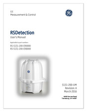
RSDetection RS-S131-200-ER0000
GE RSDetection RS-S131-200-ER0000 Manuals
Manuals and User Guides for GE RSDetection RS-S131-200-ER0000. We have
1
GE RSDetection RS-S131-200-ER0000 manual available for free PDF download: User Manual
GE RSDetection RS-S131-200-ER0000 User Manual (94 pages)
Brand:
GE
| Category:
Measuring Instruments
| Size: 2.59 MB
Table of Contents
Table of Contents
10
Table 1 - Composite Measurements
16
Figure 1 Database Tables
20
Communications
21
Figure 2 Communication Connections
21
Serial COM3
22
Table 2 LED Operations
24
Tcp/Ip
24
Time and Time Zones
21
2 Lithium-Ion Battery
25
3 Field Installation
26
Figure 3 Mounting Flange Dimensions (Inches)
26
Configuration Utility
28
Firmware
28
Firmware Updates
28
Maintenance and Service
29
Calibration
29
Calibration Check
30
Optional Battery Replacement
30
Figure 4 Battery Cover
30
Figure 5 Battery Connector
31
4 Operation
32
HPIC Principles of Operation
32
Figure 6 HPIC Diagram
32
Determining the "F" Factors
33
Energy Response
33
Figure 7 HPIC Energy Response
33
Table 3 "F" Factors for Common Isotopes
34
Table 4 Correction Factors
34
Figure 8 Saturation Curves
35
Saturation Characteristics
35
Measurement Characteristics
36
Table 5 Measurement Characteristics
36
Figure 9 Statistical Response
37
5 Software Configuration Utility
38
Figure 10 Discovery Screen
38
Figure 11 USB B Connection
39
Figure 12 Ethernet Connection
39
Available Tabs
40
Main Menu Functions
40
File Menu
40
Figure 13 Main Menu
40
Figure 14 File Menu
40
Figure 15 Application Configuration Screen
41
Database Menu
42
Figure 16 Database Menu
42
Figure 17 Database Statistics Screen
42
Utilities Menu
43
Figure 18 Delete Records Dialog Box
43
Figure 19 Utilities Menu
43
Help Menu
44
Figure 20 Date/Time Screen
44
Figure 21 Unit ID Screen
44
5.3 Configuration Utility Tabs
45
Events Tab
45
Figure 22 Events Tab on Electrometer Screen
45
Table 6 Events
46
Measurements Tab
50
Figure 23 Measurements Tab on Electrometer Test Screen
50
Table 7 Measurements
51
Configurations Tab
53
Figure 24 Configurations Tab on Electrometer Test Screen
53
Figure 25 Configuration Types
54
Figure 26 Property Grid
54
Table 8 General Configuration Parameters
55
Table 9 Scalar Measurement Configuration Parameters
55
Table 10 Composite Measurement Configuration Parameters
56
Table 11 Event Configuration Parameters
56
Table 12 Alarm Event Configuration Parameters
57
Table 13 Serial Ports Configuration Parameters
58
Table 14 Rsdetection Configuration
58
Table 15 Display Configuration Parameters
60
Table 16 Weather Station Configuration Parameters
60
Plots Tab
61
Figure 27 Plots Tab
61
Event Log Tab
62
Figure 28 Event Log
62
History Tab
63
Figure 29 History Tab
63
6 Calibration
64
Scope
64
Test Equipment and Set-Up
65
Figure 30 Rsdetection Side View Dimensions Relative to Center of Ion Chamber (Inches)
65
Table 17 Test Equipment and Materials
65
Figure 31 RS Detection Top View Dimensions Relative to Center of Ion Chamber (Inches)
66
Sensor Sensitivity Measurement
67
Figure 32 Calibration Setup with no Shield
67
Calculating Sensitivity
68
Figure 33 Calibration Setup with Shield
68
Table 18 Senor Sensitivity Calculation
68
Sample Calculation
70
Figure 34 Sample Calibration Data Sheet
72
7 XML Commands
73
Overview
73
8 Appendix
74
Configuration Utility Installation
74
Figure 35 Rsdetection Setup
74
Figure 36 License Agreement
75
Figure 37 Select Program Location
75
Pc/Network Concerns When Using Ethernet Connection
76
Discovery Screen Shows no Units
76
Figure 38 Install Check
76
No Measurements or Plots Update
77
Figure 39 Discovery - no Units
77
External Connector Pinouts
78
Power
78
Table 19 Power Connector Pinout
78
Dedicated Serial Connection
79
USB Type B
79
USB Type a (2)
79
Ethernet
79
Table 20 10 Pin Serial Connector Pinouts
79
Supported External Devices
80
FTDI VCP Driver Download and Install Procedures
80
Figure 40
81
Figure 41
81
System and Accessory Part Numbers
82
Table 21 System and Accessory Part Numbers
82
Legacy Software Configuration
83
Legacy Command Support
83
D", "L" and "E" Commands
83
Table 22 "D", "L", and "E" Command Support
83
M" Commands
84
Table 23 "M" Command Support
84
A" Commands
85
P" Commands - Configuration Commands
85
Table 24 "A" Command Support
85
Table 25 "P" Command Support
85
C"' Commands - Clear Data Queue
89
Q" Commands - Display Data Queue
89
Table 26 "C" Command Support
89
Table 27 "Q" Command Support
89
S" Commands - Display Sensor Data
91
Table 28 'S' Command Support
91
T" Commands - Set Date and Time
92
8.6.10 "U" Commands - Uptime
92
8.6.11 "V" Commands - Version
92
Table 29 'T' Command Support
92
Table 30 "U" Command Support
92
Table 31 "V" Command Support
92
Customer Support Centers
94
Advertisement
Advertisement
Related Products
GE RSDetection RS-S131-200-ERB000
GE RS734
GE RS504
GE RS744
GE RS622
GE RS46J
GE RS47GJ
GE HOTPOINT RS504GN
GE HOTPOINT RS622GN
GE Baker Hughes Reuter-Stokes Flame Tracker RS-FS-9006
GE Categories
Refrigerator
Ranges
Microwave Oven
Air Conditioner
Dishwasher
More GE Manuals
Login
Sign In
OR
Sign in with Facebook
Sign in with Google
Upload manual
Upload from disk
Upload from URL