Sign In
Upload
Manuals
Brands
GE Manuals
Medical Equipment
VIVID 3 N PRO BT03
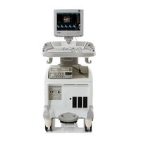
User Manuals: GE VIVID 3 N PRO BT03 Ultrasound Machine
Manuals and User Guides for GE VIVID 3 N PRO BT03 Ultrasound Machine. We have
1
GE VIVID 3 N PRO BT03 Ultrasound Machine manual available for free PDF download: Service Manual
GE VIVID 3 N PRO BT03 Service Manual (598 pages)
Brand:
GE
| Category:
Medical Equipment
| Size: 26.68 MB
Table of Contents
Table of Contents
9
CHAPTER 1 Introduction
25
Overview
25
Purpose of Chapter 1
25
Purpose of Service Manual
26
Typical Users of the Service Manual
26
Purpose of Operator Manual(S)
26
VIVID 3N Models Covered in this Manual
27
Important Conventions
28
Conventions Used in this Manual
28
Safety Considerations
30
Introduction
30
Human Safety
30
Mechanical Safety
30
Electrical Safety
31
Dangerous Procedure Warnings
32
Product Labels and Icons
33
Product Label Locations
33
Label Descriptions
35
VIVID 3N Pro/Expert External Labels
37
Labelling on Transportation Box
39
EMC, EMI, and ESD
40
Electromagnetic Compatibility (EMC)
40
Electrostatic Discharge (ESD) Prevention
40
Standards Used
41
Customer Assistance
42
Contact Information
42
CHAPTER 2 Pre-Installation
43
Overview
43
Purpose of Chapter 2
43
Console Requirements
44
Unit Environmental Requirements
44
Cooling Requirements
44
Lighting Requirements
44
Time and Manpower Requirements
44
Electrical Requirements
45
EMI Limitations
47
Probe Environmental Requirements
48
Facility Needs
49
Purchaser Responsibilities
49
Mandatory Site Requirements
50
Site Recommendations
50
Networking Pre-Installation Requirements
51
Connectivity Installation Worksheet
53
Pre-Installation Check List
54
CHAPTER 3 Installation
55
Overview
55
Purpose of Chapter 3
55
Installation Reminders
56
Average Installation Time
56
Installation Warnings
56
Safety Reminders
57
Receiving and Unpacking the Equipment
58
The Post Delivery Checklist
58
The Tilt & Shock Indicators
59
Damage in Transportation
61
Unpacking VIVID 3N Pro/Expert
62
Accessory Box Contents
64
Preparing for Installation
65
Confirming Customer Order
65
Verifying the Shipping Crate Contents
65
Component Inspection
67
System Voltage Confirmation
72
Video Formats Confirmation
73
Ensuring Protection from EMI
74
Completing the Hardware Installation
75
Connecting the Footswitch
75
Connecting Peripherals
76
Connecting Probes
81
Connecting the ECG
83
Connecting the Unit to a Power Source
85
Switching the System ON/OFF
87
Software Installation
89
Installing Application and Operating System Software
89
System Configuration
90
Adjusting the Display Monitor
90
Irection Fk091075, Revision IVID 3N Pro Xpert Ervice Anual
90
Hospital Info Tab
90
System Tab
91
Connectivity Tab
92
Archive Tab
92
Annotation Settings Tab
94
System Options Tab
95
Printers Tab
96
VCR/ECG Tab
99
Technical Support Tab
100
Technical Support History Tab
102
Connectivity Setup
103
Introduction
103
Physical Connection
103
Setting up for Connectivity
105
Setting up the Network Connection
108
Setting up for Communication with a Prosolv Workstation
110
Connecting Directly to Echopac PC
117
Image Vault Server
118
Validating Echopac or Image Vault Operation
120
Storing and Transporting the Unit
121
Disconnecting the Unit When Storing
121
Preparing the Unit for Transport
121
Safety Precautions for Moving the VIVID 3N Unit
122
Completing the Installation Paperwork
123
System Installation Details
123
Product Locator Installation
124
User Manual(S)
125
The Post Delivery Check List
126
CHAPTER 4 Functional Checks
129
Overview
129
Purpose of Chapter 4
129
General Procedures
130
Power ON/OFF and Boot-Up Tests
130
Diagnostic Power Supply Test
130
Functional Check
131
Basic Controls
131
Peripherals
132
Mechanical Functions
134
Back End Processor Tests
135
Image Testing: 2D/M/Cfm/Doppler
139
3S Probe Image Quality Tests
139
7S Probe Image Quality Tests
146
C358 Curved Probe Image Quality Tests
147
739L Probe Image Quality Tests
149
Probe 10S Image Quality Tests
153
Pencil) Probe Image Quality Test
153
System Turnover Checklist
154
Software Configuration Checks
154
Site Log
161
CHAPTER 5 Components and Function (Theory)
163
Overview
163
Purpose of Chapter 5
163
General Information
164
Block Diagrams
165
System Block Diagrams
168
Front End
169
General Information
169
Front End Crate Block Diagram- RFI
170
Front End Crate Block Diagram - RFT
171
Front Board Assembly (FB)
178
MUX Board
180
Beamformer Board (BF)
181
Radio Frequency Interface (RFI) Board
182
Front End Controller Board (FEC)(RFT)
184
RF and Tissue Processor Board (RFT)
185
Image Port Board (IMP)
186
Radio Frequency Interface Board (RFI)
186
Back Plane Board (Motherboard)
186
Back End Processor
187
Introduction
187
Central Processing Unit (CPU)
191
Keyboard Controller
194
Multifunction I/O Controller
195
Frame Grabber (RFI Systems Only)
195
Pc2Ip
195
Plug and Scan Card and Battery
195
Network Onboard
195
SCSI Card
195
Floppy Drive
196
Hard Disk
196
Magneto-Optical Drive (MOD)
197
CD Read Write (CDRW)
197
ECG Module
197
Modem
198
PC-VIC Assembly
199
External Peripherals
201
Introduction
201
VIVID 3N Power Distribution
202
Electrical Power
202
AC System
203
AC Distribution Box
205
Front End DC Power Distribution
206
Front End Cooling System
208
General Description
208
Location in the Unit
208
Common Service Platform
209
Introduction
209
Ilinq Interactive Platform Features
209
Global Service User Interface (GSUI)
210
Restart VIVID 3N Pro/Expert after Diagnostics
211
CHAPTER 6 Service Adjustments
213
Overview
213
Purpose of Chapter 6
213
Input AC Voltage Configuration
214
Secondary Voltage Configuration
214
AC Input Cord
214
Front End Voltages and Signal Indicators
215
RFI Leds
217
Image Port (IMP) Leds
218
Front End Controller (FEC) Leds
218
RF and Tissue Processor (RFT)
218
Beamformer (BF)
219
Channels Multiplexer (MUX)
219
Front Board Assembly (FB)
220
Back End Power Supply Voltages
221
VIC Video Signal Setting
221
Video Format Confirmation
221
Monitor Operation
222
VIVID 3N Pro/Expert Samsung 15" and 17" Monitor Operation
222
VIVID 3N 15" Monitor Operation
226
VIVID 3N 17" Monitor Operation
228
Image Quality Calibration
231
Image Quality Calibration for the VIVID 3N 15" Monitor
231
Image Quality Calibration for the VIVID 3N 17" Monitor
232
Calibration
233
Accessing the Calibration Options
234
Monitor Calibration
235
Beamformer Calibration
236
Video Grabbing Calibration
237
CHAPTER 7 Diagnostics/Troubleshooting
239
Overview
239
Purpose of Chapter
239
Diagnostics
240
Diagnostic Tools
240
Diagnostic Procedure Summary
240
Accessing the Diagnostic Menu
241
Performing Front End (FE) Diagnostics
243
Accessing the Front End Diagnostic Options
244
Radio Frequency Interface (RFI) Diagnostic Tests (for RFI Configuration)
250
Image Port (IMP) Diagnostic Tests
251
VME Bus (VME) Diagnostic Tests( RFT Configuration)
253
RFT Diagnostic Tests (RFT Configuration)
255
Front End Controller (FEC) Diagnostic Tests (RFT Configuration
257
Beamformer (BF) Diagnostic Tests
261
Front Board Assembly (FB) Diagnostic Tests
264
MUX Diagnostic Tests
288
H/W Report
307
Current Report
308
Performing Back End Diagnostics on the System
309
Accessing the Back End Diagnostic Options
309
Audio (Doppler Sound Driver) Diagnostic Test
311
Ecg/Phono Diagnostic Test
312
Extended Keyboard Diagnostic Test
314
Keyboard Diagnostic Test
317
Media Driver Diagnostic Test
318
Computer Diagnostic Test
321
UPS Test
324
Checking the Network Adaptors from Windows Device Manager
325
Common Service Interface
326
Ilinq Interactive Platform Features
326
Global Service User Interface
326
Error Logs Page
330
Diagnostics Page
339
Irection Fk091075, Revision IVID 3N Pro Xpert Ervice Anual
339
Calibration Page
350
Configuration Page
351
Utilities Page
352
Replacement Page
365
PM Page
365
Automatic Error Log
366
Saving the Logger Report
367
Sending the Logger Report
368
CHAPTER 8 Replacement Procedures
371
Overview
371
Purpose of Chapter 8
371
Cover Replacement Procedures
372
Overview of Covers
372
Side Covers Replacement Procedures
374
Front Cover and Air Filter Replacement Procedures
375
Rear Cover Replacement Procedures
377
Connector Panels Cover Replacement Procedures
378
Top Cover (Lower Section) Replacement Procedures
379
Gas Spring Cover Replacement Procedure
383
Bottom Keyboard Cover Replacement Procedure
384
Speaker Cover Replacement Procedure
386
Control Console Bottom Cover (Upper Section) Replacement Procedure
387
Control Console Top Cover Replacement Procedure (Upper Section)
390
Direction Fk091075, Revision
390
VIVID
390
P /Esm
392
Screws, as Shown in Figure 8-14 "Gas Spring Cover Screws" on Page
392
And VGA Cables at Rear of Control Console" on Page
392
Right and Left Probe Holders Replacement Procedure
393
Front Handle Replacement Procedure
394
Rear Handle Replacement Procedure
396
Control Console Components Replacement
398
VIVID 3N Monitor 15" Replacement - Procedure
398
VIVID 3N 17" Monitor Replacement - Procedure 1
401
VIVID 3N 17" Monitor Replacement - Procedure 2
405
Keyboard Replacement Procedure
408
Keypad Replacement Procedure
409
Keycaps (External Keyboard) Replacement Procedure
410
Rotary Knob (External Keyboard) Replacement Procedure
411
Trackball Replacement Procedure
413
Speaker Replacement Procedure
414
Front End Parts Replacement
415
Front End Boards Replacement Procedure
415
TR4 Boards Replacement Procedure
417
DC Power Supply Replacement Procedure
419
TX Power Supply Replacement Procedure
420
Front End Crate Replacement Procedure
421
Fan Replacement Procedure
423
Direction Fk091075, Revision
424
Irection Fk091075, Revision IVID 3N Pro Xpert Ervice Anual
424
Back End Parts Replacement
425
BEP1 Cover Replacement Procedure
432
BEP2 Cover and Octopus Card Holder Replacement Procedure
434
Plug & Scan Board Replacement Procedure
438
Plug & Scan Battery Replacement Procedure
439
VGA AGP Board Replacement Procedure
441
SCSI Board Replacement Procedure
442
PC2IP Board Replacement Procedure
444
Keyboard Control Board Replacement Procedure
445
CDRW Drive Replacement Procedure
446
MO Drive Replacement Procedure
448
ECG Module Replacement Procedure
450
PC-VIC Replacement Procedure
457
Hard Disk Replacement Procedure
459
Lower Section Components Replacement
462
AC Distribution Box Replacement Procedure
462
AC Input Box Replacement Procedure
464
Keyboard or Monitor Cable Replacement Procedure
465
AC, BEP or FE Cable Replacement Procedure
466
Gas Spring Cable Replacement Procedure
467
Up/Down Handle Replacement Procedure
469
Gas Spring Replacement Procedure
475
Front Wheel Replacement Procedure
478
Rear Wheel Replacement Procedure
483
Software Loading
485
Software Installation/Upgrade Procedure
485
Peripherals
486
B/W Video Printer Replacement Procedure
486
Sony VCR Replacement Procedure
491
JVC VCR Replacement Procedure
496
Sony up 2950 MD & 2800P Color Video Printer Replacement Procedure
504
Sony UP-21MD Color Video Printer Replacement Procedure
515
HP Deskjet 6122 Color Printer Replacement Procedure
524
CHAPTER 9 Renewal Parts
527
Overview
527
List of Abbreviations
528
Optional Service Parts Kits Delivered with Unit
529
AC Power Overview
530
Front End Parts
533
Global Modem
534
CHAPTER 10 Periodic Maintenance
565
Overview
565
Warnings
565
Why Perform Periodic Maintenance Procedures
566
Keeping Records
566
Periodic Maintenance Schedule
567
How Often Should PM Procedures be Performed
567
Tools Required
570
Special Tools, Supplies and Equipment
570
System Periodic Maintenance
571
Preliminary Checks
571
Functional Checks
572
Input Power Checks
573
Cleaning
574
Physical Inspection
575
Diagnostic Checks (Optional)
576
Probe Maintenance
577
Probe Checks
577
Probe Handling
577
Basic Probe Care
578
Probe Cleaning
578
Returning and Shipping of Defective Probes
581
Electrical Safety Tests
582
Safety Test Overview
582
GEMS Current Leakage Limits
583
Outlet Test Wiring Arrangement - USA & Canada
584
Grounding Continuity
584
Chassis Current Leakage Test
586
Isolated Patient Lead (Source) Leakage - Lead-To-Ground
588
Isolated Patient Lead (Source) Leakage - Lead-To-Lead
589
Isolated Patient Lead (Sink) Leakage - Isolation Test
589
Probe Current Leakage Test
591
Advertisement
Advertisement
Related Products
GE LOGIQ LP6 PRO BT11
GE ProSpeed S
GE ProSpeed SX Lemage
GE ProSpeed Lemage Supreme
GE ProSpeed VX
GE ProSeed Accell El
GE ProSpeed ProSeed
GE ProSpeed Advantage
GE ProSeed SA
GE DINAMAP PRO 100V2
GE Categories
Refrigerator
Ranges
Microwave Oven
Air Conditioner
Dishwasher
More GE Manuals
Login
Sign In
OR
Sign in with Facebook
Sign in with Google
Upload manual
Upload from disk
Upload from URL