Sign In
Upload
Manuals
Brands
GE Manuals
Fan
X353-5B
GE X353-5B Lift Fan Aircraft Manuals
Manuals and User Guides for GE X353-5B Lift Fan Aircraft. We have
1
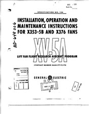
GE X353-5B Lift Fan Aircraft manual available for free PDF download: Installation, Operation And Maintenance Instructions
GE X353-5B Installation, Operation And Maintenance Instructions (460 pages)
Lift Fan Flight Research Aircraft Program
Brand:
GE
| Category:
Fan
| Size: 22.02 MB
Table of Contents
Section 1
3
Table of Contents
3
Section 2
9
General
12
Introduction
12
Replacement of Parts
12
Scope
12
Basic Fan Description
14
General
14
System Description
14
System Orientation
16
Blade Platforms
17
Blade Retainer Rings
17
Rotor Blades
17
Rotor Component Description
17
Shaft and Disc
17
Carrier Segment Seal
18
Torque Band Segments
18
3Lade Carrier Pins
19
Blade Shroud Cover
19
Lock Pin
19
Lock Strip
19
Bucket Carrier Tabs
20
Bucket Tip Shrouds
20
Turbine Bucket Carrier Assembly
20
Turbine Buckets
20
Balance Weight
21
Tie Bolts, Washers and Nuts
21
Front Frame Description
22
Hub
22
Bearing System
23
Housing - Roller Bearing
23
Grease Seals
24
Grease Shield - Ball Bearing
24
Retainer Seal - Ball Bearing
24
Boss-Speed Picek-Up Sensor 1 - 2 . 1
25
Grease Shield-Roller Bearing
25
Magnetic Rotor Speed Pick-Up Sensor
25
Struts
25
Bellmouth
27
Clevis - Scroll Mounting
28
Pin - Support Beam
28
Shim - Scroll Mounting Clevis
28
Shoulder Bolt - Scroll Mounting
28
Forward Compressor Seal
29
Insulation Blanket
29
Inlet Vane Description
30
Scroll Description 99.99.99
32
Rear Frame
36
Honeycomb Air Seals
37
Exit Louver System
38
Insulation Blanket - Inner
38
Insulation Blanket - Outer
38
Turnbuckle - Rear Frame to Scroll
38
Exit Louvers
39
Actuator Linkage
40
Typical Fan-In-Wing X353-5B Installation
41
System Orientation
43
Lift Fan Rotor Component
44
Lift Fan Front Frame
45
Lift Fan Scroll, View of Inlet
47
Lift Fan Scroll, Top View
49
Exit Louver System
53
Diverter Valve Description
54
Diverter Valve Actuation System
59
Sketch of Actuation Linkage in Straight-Through
60
And Diverted Positions
60
Bearing, Ball, Inner Race
61
Bearing, Ball, Outer Race
61
General
61
Special Tools
61
REAR Fram
62
Rotor
63
Rotor Balance Arbor
64
Roller Bearing Outer Race Puller
64
Rotor Turnover Dolly
65
Ball Bearing Inner Race Puller
66
Rotor Vertical Lift Fixture
67
Roller Bearing Inner Race Puller
67
Spanner Wrench
68
Ball Bearing Outer Race Puller
68
Lift Fan Shipping Container
70
Lift Fan Transportation Dolly
70
Assembly of X353-5B
75
Assembly Tooling
75
General Assembly Procedure
75
Scope
75
Disc and Shaft Assembly
76
Rotor Assembly (Reference Figure 4.2)
76
Assembly of Blade Platforms
78
Assembly of Rear Blade Retainer Ring
78
Assembly of Torque Band Segments
78
Assembly of Carrier Seals
79
Assembly of Bucket Carrier Segments
80
Assemble Insulation Blanket
85
Orientation
85
Assembly of 810 Scroll Mounts
87
Inspection and Adjustment of the Scroll to the Front Frame
89
Assembly of Scroll Finger Seals I
90
Assemble Scroll Seals and Air Seal Supports
91
Assembly of Scroll Insulation
91
Final Assembly of Scroll to Front Frame
91
Assemble Honeycomb Air Seal
92
Assembly of Thrust Bearing Outer Race
92
Assemble Rear Frame Insulation Blankets
93
Assembly of Rear Frame Air Seal Segments
94
Assemble Bearing Inner Races to Rotor Shaft
95
Assemble Rotor to Front Frame and Scroll
95
Assemble the Rotor to the Thrust Bearing
96
Assemble the Roller Bearing
97
Clearance Inspection Prior to Assembly of Rear Frame
98
Assembly of Rear Frame to Front Frame
99
Clearance Inspection after Assembly of Rear Frame
100
Setting of Nozzle Area Adjustment Vanes
101
Exit Louver Assembly
102
Orientation of the Exit Louver Push Rods
102
Assemble Bushings to Supports
103
Assemble Louver Port Bushing to Strut
103
Assembly of Exit Louver Push Pods
103
Assemble Exit Louver #14
104
Assemble the Lever Arms to Louvers
104
Assemble Louver #13
105
Assemble Louver #38
105
Assembly of Remaining Louvers
105
Assembly of Circular Vane
106
X353-5B Propulsion System
282
1.1
289
General
292
Introduction
292
General
297
Replacement of Parts
297
Scope
297
Basic Fan Description
299
System Orientation
301
Rotor Component Description
301
Disc Description
301
Blade Retainer Rings
302
Rotor Blade Description
302
Bucket Carrier Description
303
Torque Band Description
303
Bolt, Blade-To-Carrier
304
Bolt, Torque-Band-To-Carrier
304
Frame Description
304
Front Frame Description
304
Shaft
305
Bearing System
306
Grease Seals
307
Grease Shield
307
Retainer, Ball Bearing
307
Retainer, Roller Bearing
307
Spacer, Front Frame to Ball Bearing
307
Speed Generator Disc
308
Magnetic Sensor - Rotor RPM
308
Mount - Front Frame to Rear Frame (6 O'clock)
308
Air Seal - Rotor
309
Rear Frame
310
Support - Front Frame to Rear Frame
309
Support - Front Frame to Rear Frame (6 O'clock)
309
Insulation Blanket - Rear Frame
311
Cover Front Frame to Rear Frame
312
Turbine Inlet Scroll
312
Scroll Blank off Plates
313
Insulation Blanket- Scroll
313
Scroll Mounting
313
Clevis
314
Center Mounts
315
End Mounts
315
Scroll End Covers
315
Scroll Seal Segments
316
(C) Disc. Shaft and Speed Generator, (D) Rim Bolt
320
Spacers
320
Hub, (B) View of Aft Side of Front Frame Hub
323
Mount, (B) Support Arm
330
3.1 General
332
Special Tools
332
Bearing, Inner Race, Ball and Roller
333
Pitch Fan
334
Rotor Balance Arbor
334
Rotor Shaft Puller
334
Ball and Roller Bearing Outer Race Puller
334
Front Frame and Rotor Shaft Line up Pins
334
Rotor Support Stand
334
Assembly Procedure
341
Disc Assembly
342
Blade and Torque Band Assembly
343
Carrier Assembly
344
Rotor Inspection
345
Torque Procedure - Rim Bolts
346
4.10 Front Frame Assembly
347
Mount Assembly
348
4.13 Scroll Seals to Front Frame Adjustments
349
4.15 Scroll Support Arm to Clevis Adjustment
349
Mount to Front Frame Adjustment
349
4.16 Scroll Assembly
350
Cover Assembly
350
Inspection - Scroll to Front Frame
350
Magnetic Speed Pickup Bushing Assembly
350
Air Seal Grinding Instruction
351
4.22 Air Seal Radial Inspection
351
4.23 Disc Bearing Assembly
351
Shaft Bearing Assembly
352
Shaft to Disc Assembly
352
Rotor Adjustments
353
Rotor Seal Clearance Inspection
353
Rotor to Front Frame and Scroll Assembly
353
4.29 Rear Frame to Front Frame and Scroll Assembly
354
Insulation Blanket Assembly
355
Rear Frame to Front Frame Concentricity Inspection
355
Inspection - Rotor Turbine Shroud to Rear Frame
356
Speed Pickup Assembly
356
Installation Design Data
381
X376 PITCH TRIM CNTDOL FAN Disassembly
382
6.1 Removal from Shipping Container
382
6.2 Remove Rear Frame
382
Remove Rotor
382
Disassemble Front Frame
383
Remove Air Seals
383
Remove Covers
383
6.8 Remove Speed Pick-Up
383
6.9 Remove Mounts
383
Disassemble Rotor
383
6.11 Remove Carrier Segments
383
Remove Blades
383
Remove Shaft
384
Scroll Disassembly
384
Inspection, Repair and Replacement
386
General
386
Cleaning and Inspection
386
7.3 Cleaning of Bearings
386
Fluorescent-Penetrant Method of Inspection (Zyglo)
388
General
388
Cleaning Prior to Application of Fluorescent-Penetrant
388
Application of Fluorescent-Penetrant Oil
388
Cleaning of Titanium
389
7.10 Periodic Inspection Requirements
408
Pitch Fan Serial Numbers
408
Testing after Overhaul or Maintenance
409
Introduction
409
J85-GE-5 Engine Calibration Tests
409
System Functional and Performance Tests
419
8.4 Fan Performance
441
Operating Limits
460
Advertisement
Advertisement
Related Products
GE XV-5A
GE X376
GE X3
GE XL44 JGBP26GEN
GE XL44 JGBS72
GE XL44 JGBP25GEN
GE XL44 JGBS07
GE XI44 JGBP34GEP
GE X Series
GE XL44 JGBC18
GE Categories
Refrigerator
Ranges
Microwave Oven
Air Conditioner
Dishwasher
More GE Manuals
Login
Sign In
OR
Sign in with Facebook
Sign in with Google
Upload manual
Upload from disk
Upload from URL