Sign In
Upload
Manuals
Brands
Hitachi Manuals
Inverter
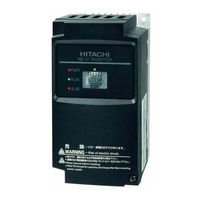
NES1-040HB
Hitachi NES1-040HB Manuals
Manuals and User Guides for Hitachi NES1-040HB. We have
1
Hitachi NES1-040HB manual available for free PDF download: Quick Reference Manual
Hitachi NES1-040HB Quick Reference Manual (295 pages)
NE-S1 SERIES
Brand:
Hitachi
| Category:
Inverter
| Size: 2.95 MB
Table of Contents
Quick Reference Guide
1
Table of Contents
3
Chapter 1 Safety Instructions
8
Safety Instructions
8
Precautions Concerning Electromagnetic Compatibility (EMC)
14
Precautions Concerning Compliance with UL and Cul Standards
19
Chapter 2 Inspection of the Purchased Product
20
Method of Inquiry and Product Warranty
23
Chapter 3 Exterior Views
24
Exterior Views and Names of Parts
26
Name of each Portion (Removing the Front Cover)
27
Chapter 4 Installation
29
Precautions for Installation
31
Chapter 5 Wiring
34
Precautions for Wiring
36
How to Attach and Remove the
37
How to Attach the Exclusive Operator (NES1-OP)
38
How to Attach the Exclusive Operator
38
Wiring and Terminal Description
39
Mains Wiring
42
Wiring of the Control Circuit
47
Connection with the Programmable Controller (PLC)
49
Notes on Using Multiple Inverters
50
Chapter 6 Operation
52
Precautions of Operation
54
Confirmation before Power up the Inverter
55
Changing Parameters
55
Power up the Inverter
56
How to Operate the Inverter
57
Motor Operation
64
Test Run with the Motor
70
When Tripping Occurs
72
Chapter 7 Explanation of Functions
76
Monitoring the Data
76
Output Frequency Monitoring (D001)
76
Output Current Monitoring (D002)
76
Rotation Direction Monitoring (D003)
76
Process Variable (PV), PID Feedback Monitoring (D004,A071,A075)
76
Output Voltage Monitoring (D013)
78
Input Power Monitoring (D014)
78
Cumulative Power Monitoring (D015,B078,B079)
78
Cumulative Operation RUN Time Monitoring (D016)
78
Cumulative Power-On Time Monitoring (D017)
78
Heat Sink Temperature Monitoring (D018)
78
Dual Monitoring (D050,B160,B161)
79
Trip Counter (D080)
79
Warning Monitoring (D090)
80
DC Voltage Monitoring (D102)
80
Electronic Thermal Overload Monitoring (D104)
80
Using the Basic Functions
81
Frequency Source Setting and Output Frequency Setting
81
Run Command Source Setting (A002/A202,C001 to C005,F004)
82
Keypad Run Key Routing (F004)
82
Rotational Direction Restriction (B035)
82
Stop Mode Selection (B091,F003/F203,B003,B007,B008)
83
Acceleration/Deceleration Time Setting (F002/F202, F003/F203, A004/A204, C001 to C005)
83
Base Frequency Setting (A003/A203, A082/A282)
84
Using the AVR Functions (A081/A281, A082/A282, A083, A084)
84
Maximum Frequency Setting (A004/A204)
86
Carrier Frequency Setting (B083)
86
Setting the Intelligent I/O Terminal Function
87
Intelligent Input Terminal Setting (C001 to C005)
87
Input Terminal Response Time (C160 to C164)
88
Intelligent Output Terminal Setting (C021,C026)
88
Using the Analog Terminal
91
Analog Input (O/OI)
91
External Analog Input (O/OI) Filter Setting (A016)
91
Analog Command Holding Function (AHD) (C101,C001 to C005)
92
Analog Input Adjustment (C081)
93
Start/End Frequency Setting for External Analog Input (A011 to A015)
93
FM Terminal (C027,C030,C105,B081)
94
To Drive the Motor
95
V/F Characteristic Curve Selection (A044/A244,B100 to B113)
95
Torque Boost Setting (A041/A241,A042/A242, A043/A243,H003/H203,B H004/H204)
97
Start Frequency Setting (B082)
99
Reduced Voltage Start Function (B036,B082)
99
Frequency Upper Limit Setting (A061/A261,A062/A262)
101
Jump Frequency Function (A063 to A068)
101
Acceleration/Deceleration Hold Frequency Setting (A069,A070,A154,A155)
102
Permission of Run Command Function (ROK) (C001 to C005)
102
Multispeed Select Setting (CF1 to CF3 and SF1 to SF3)
103
Acceleration/Deceleration Curve Selection (A097,A098,A131,A132)
105
Frequency Operation Function (A141,A142,A143,A001,A076)
106
Frequency Addition Function (A145,A146,C001 to C005)
107
Remote Control Function (up and DWN) (C101,C001 to C005)
107
V/F Gain Setting (A045/A245,A082/A282)
108
PID Function (A071 to A078,C044,C052,C053)
109
Energy-Saver Operation (A085,A086)
114
Stabilization Constant Setting (H006/H206,A045,B083)
114
Nd Motor Control Function (SET) (C001 to C005)
115
Functions Related to the Operator Display
120
STOP Key Enable (B087)
120
Forcible-Operation from Digital Operator (OPE) Function
120
Forcible-Operation from Terminal (F-TM) Function
121
Action Selection in Case of External Operator Disconnection (B165)
121
Initial-Screen Selection (Selection of the Initial Screen to be Displayed after Power-On)
121
B038
121
Select Automatic Return to the Initial Display (B164)
122
NES1-OP Display Selection (B150)
122
Data Read/Write Selection (B166)
122
Display Limitation Function (DISP) (C001 to C005)
122
Function Code Display Restriction (B037)
123
Button Sensitivity Selection (C151)
124
Scroll Sensitivity Selection (C152)
125
Functions about Restarting
126
Retry (under Voltage , over Current / over Voltage)
126
Deceleration and Stopping at Power Failure (Nonstop Deceleration at Instantaneous Power Failure) (B050 to B054)
133
Set Functions Related to Protection and Warning, each Output Signal
135
Trip Signal (AL)
135
Overload Restriction/Overload Notice (B021 to B026,C001 to C005,C021,C026,C040,C041)
138
Overcurrent Restraint (B027)
139
Over Voltage Supression During Deceleration (B130 to B134)
140
Automatic Carrier Frequency Reduction (B083,B089)
142
Running Signal (RUN) (C021)
143
Frequency Arrival Signals (FA1, FA2, FA3) (C021,C042,C043)
143
Running Time over and Power-On Time over Signals (RNT and ONT)
145
Communication Line Disconnection Signal (Ndc) (C021,C026,C077)
147
Starting Contact Signal (FR) (C021,C026)
147
Heat Sink Overheat Warning Signal (OHF) (C021,C026,C064)
147
Low-Current Indication (LOC) Signal (C021,C026,C038,C039)
148
Inverter Ready Signal (IRDY) (C021,C026)
148
Forward Rotation Signal (FWR) (C021,C026)
149
Reverse Rotation Signal (RVR) (C021,C026)
149
Major Failure Signal (MJA) (C021,C026)
149
Window Comparators (WC) (Detection of Terminal Disconnection:DC)
150
Frequency Command Source (FREF)
151
RUN Command Source (REF)
151
2Nd Motor in Operation (SETM)
151
Ground Fault Detection (C155)
151
Out Phase Loss Detection (C157)
151
Chapter 8 Communication Functions
153
Communication Specification
155
Connecting the Inverter to Modbus
156
Modbus Setting Procedure
157
Modbus Communication Parameter
158
Modbus Protocol Reference
159
Explanation of Function Codes
163
Re-Calculate the Internal Variable
172
Modbus Data Listing
173
Chapter 9 Error Codes
195
Indication of the Error
197
Error Codes and Troubleshooting
199
Warning Codes for Digital Operator
201
Other Display for Digital Operator
202
Chapter 10 Troubleshooting
203
Troubleshooting Tips
205
Chapter 11 Maintenance and Inspection
212
Precautions for Maintenance and Inspection
212
Daily and Periodic Inspections
213
Ground Resistance Test with a Megger
214
Withstand Voltage Test
214
Methods of Measuring the Input/Output Voltages, Current, and Power
215
Current, and Power
215
Capacitor Life Curves
216
Chapter 12 Specifications
218
Specifications
218
Dimensions
222
Derating Curves
224
Chapter 13 Option
228
Digital Operator
269
Top Cover for Exclusive Use of NE-S1Series : NES1-FFM-M
284
Appendix
289
Index
293
Advertisement
Advertisement
Related Products
Hitachi NES1-004SB
Hitachi NES1-015SB
Hitachi NES1-022SB
Hitachi NES1-004LB
Hitachi NES1-002LB
Hitachi NES1-015LB
Hitachi NES1-022LB
Hitachi NES1-004HB
Hitachi NES1-015HB
Hitachi NES1-022HB
Hitachi Categories
Projector
Air Conditioner
Drill
Power Tool
TV
More Hitachi Manuals
Login
Sign In
OR
Sign in with Facebook
Sign in with Google
Upload manual
Upload from disk
Upload from URL