Sign In
Upload
Manuals
Brands
Hitachi Manuals
Printer
PXR
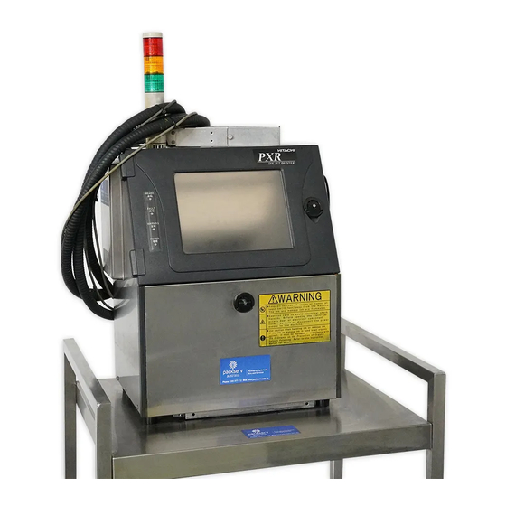
Hitachi PXR Manuals
Manuals and User Guides for Hitachi PXR. We have
1
Hitachi PXR manual available for free PDF download: Service Manual
Hitachi PXR Service Manual (232 pages)
Brand:
Hitachi
| Category:
Printer
| Size: 5.3 MB
Table of Contents
Service Manual
1
Revision of PXR Service Manual
2
Contents
3
Introduction
7
Safety Precautions
7
Safety Precautions
8
Installation ···········································································································
12
PXR-P Usage Precautions
14
External Views (PXR-D, PXR-H)
15
Structure of each Part in the Main Body
15
Main Body Internal (PXR-D, PXR-H)
16
External Views (PXR-P)
17
Main Body Internal (PXR-P)
18
Print Head
19
Installation
20
Notes about UL
20
The Usable Power Cable
20
Wiring of Power Supply
20
Installation Procedure (PXR-D, PXR-H)
23
Installation Procedure (PXR-P)
24
Air Connection and Air Pressure Adjustment (at the Time of Installation)
25
Ink Replenishment (at the Time of Installation)
27
Disposition of Makeup Ink Inside Main Ink Tank (at the Time of Installation)
27
Maintenance Work
28
Setting of Maintenance Mode by Service Personnel
28
Features of the Service Personnel Maintenance Mode
30
System Environment Setup
31
Conditions Set by the Ink Type 1
32
Adjustment/Operational Checkout
34
Excitation Adjustment
34
Charging Voltage Confirmation
36
Phase Margin Test
37
Auto Phase Gain Adjustment
39
Level Sensor Confirmation
41
Model PXR-D and PXR-P Level Sensor Confirmation
41
Model PXR-H Level Sensor Confirmation
42
Heating Unit Confirmation
44
Test of Solenoid Valve/Pump
45
Download
46
Download ············································································································
47
Calibration of Viscometer
48
Confirmation of the Ink Viscosity Coefficient
50
“Coefficient” Confirmation Method
50
Operation Test of Viscometer
51
Ink Concentration Control
52
System Reset
53
Back up
54
Password Protection
56
Turn on the Power
56
Unit Information
56
Handling of the Warning “Product Speed Matching Error”
57
Language Registration
58
Fault / Warning Log Management Code
60
Software Option Setup
62
Construction of Controlling Part
64
Maintenance of Controlling Part
64
Controller Part (Cover-Opening State)
65
Controller Part
66
EZJ104 Board (Controller Board)
66
Function
66
Check Points
66
Replacement Procedure of EZJ104 Board in a State Allowing no Back up
68
EZJ104 Board External Views
69
Battery ············································································································
70
Power Supply for LCD Backlight
70
Control Panel
71
Replacement Procedure of EZJ93 Board
72
Engine Part
72
Notes in Case of the EZJ93 Board Replacement
72
EZJ93 Board (MPU Board)
72
Replacement Procedure of EZJ93 Board in a State Allowing no Back up
74
EZJ93 Board External Views
75
EZJ94 Board (NH Board)
76
EZJ94 Board External Views
76
Note at the Replacement
76
Setting of Switch/Check Point/Led Display and the Like
76
Difference between the EZJ94 Board and the EZJ94DH Board
77
EZJ95 Board (I/O Board)
78
Circuit Diagram of EZJ95
80
EZJ99 Board (Optional Board)
81
Included Parts
81
Setting Procedure
81
Notes for Replacement
84
Setting of Switch
84
EZJ105 Board
85
Caution against an Electric Shock
86
High Voltage Power Supply
86
Multiple Power Supply
86
Fan Replacement Procedure
87
Configuration of the Model PXR-P
88
Configuration of the Model PXR-D and the Model PXR-H
88
Exhaust Filter Replacement Procedure
89
Replacement Interval
89
General Structure of Circulation System
91
Maintenance of Circulation System (PXR-D, PXR-H)
91
Approach to the Parts on the Front Side of the Equipment
92
Approach to the Parts on the Rear Side of the Equipment
93
Main Ink Tank Replacement Procedure
94
Pressure Relief Valve Replacement Procedure
96
“ICU Joint” Structure and Handling
97
Joint Structure and Handling
97
Procedure for Installing and Removing the Tube
97
Procedure for Installing and Removing the ICU Joint (at Occurrence of Damage)
97
“Filter Joint” Structure and Handling
98
Pump Unit Replacement Procedure
99
Solenoid Valves Replacement Procedure
101
Pressure Sensor Replacement Procedure
103
Circulation Unit Replacement Procedure
104
Troubleshooting When Fault Occurs in Viscometer
107
Viscometer Removal Procedure
107
Attention to the Model PXR-H
109
Explanation of the Viscometer Label
109
Disassembling and Washing Viscometer
110
Viscometer Assembly Procedure
111
Viscometer Attaching Procedure
111
Proximity Sensor Replacement Procedure
112
Replacing Thermistor
112
Print Head Replacement Procedure
113
Troubleshooting Procedure for the Circulation System
115
Repairing Method When the Circulation Route Is Dry or Sticks
120
Repairing Method for the Supply Pump
120
Cleaning Method for the Solenoid Valve
120
Procedure for Repairing the Circulation Pump
121
Procedure for Repairing the Recovery Pump
121
Repairing Method for the Makeup Ink Pump
121
Maintenance of Circulation System
122
Main Ink Tank and Ink Reservoir Replacement Procedure
125
Air Joint Structure and Handling
129
Solenoid Valve for Circulation Unit
130
Solenoid Valve for Stirrer
130
Replacement Procedures for Pressure Sensor and Pressure Switch for Air
132
Explanation of Viscometer Label
136
Attention to the Model PXR-P Viscometer
136
Stirrer Replacement Procedure
137
Repairing Method for each Solenoid Valve and Pump Using Solvent Pump
140
Outline Structure of Print Head and How to Remove each Cover
141
Print Head-Related Maintenance
141
Nozzles Replacement Procedure
142
Nozzle Drive Conditions
144
Deflecting Base Replacement Procedure
146
Cover Switch Replacement Procedure
149
Knack of Infusing the Silicone
149
Storage of the Dispenser
149
Sealing Valve (MV9) Replacement Procedure
150
Heating Unit Replacement Procedure
152
Gutter Base Group Replacement Procedure
153
Head Base Replacement Procedure
154
Replacing EZJ98 Board (APH Sensor Board)
156
Table of Contents
158
Troubleshooting
158
Troubleshooting List
158
Faults – Ink-Stop Type
160
Ink Low
160
Main Ink Tank too Full
161
Makeup Ink Low
162
Replenishment Time-Out
163
Ink Drop Charge too Low
164
No Ink Drop Charge
165
Noise Fault M/S
166
Deflection Voltage Leakage
167
Deflection Voltage Fault
169
DC Power Supply Fan Fault
170
Charge Voltage Fault
171
F Memory Fault M/S/9
172
Internal Communication Error S
172
Hardware Error C
173
Ink Heating too High
174
Heating Unit Sensor Fault
175
Ink Heating Current Fault
176
Ambient Temperature Sensor Fault
177
Viscometer Temperature Sensor Fault
177
Pump Motor Fault
178
Cooling Fan Fault
178
Faults - Print-Stop Type
179
Print Overlap Fault
179
Cover Open
180
Improper Sensor Position
181
Target Sensor Fault
182
Target Spacing too Close
183
Print Data Changeover in Progress S/C/M/V
183
Blank Print Items
184
Excessive Format Count
184
Substitution Character Undefined
185
Ink Drop Charge too High
186
Internal Communication Error C/M
188
Warning Conditions (Printing Continuously Performed)
189
Ink Shelf Life Exceeded
189
Operating Temperature too High/Too Low
190
Ink Heating too Low
191
Battery Low
192
Product Speed Matching Error
192
Ink Pressure Low
193
Ink Pressure High
194
Viscosity Reading Instability
195
Viscosity Readings out of Range
196
High Ink Concentration
197
Low Ink Concentration
197
Excitation V-Ref. Review
198
High Air Pressure
198
Faults - no On-Screen Indications
199
Chipped Print (Lower Dots)
199
Chipped Print (Upper Dots)
200
Varying Character Height
201
Increased Character Distortion
202
Disordered Characters
203
Ink Leakage/Blowout
204
Printing Initiation Failure in Ready-For-Printing State (no Prints)
205
No Ink Ejection from Nozzle
206
Freeze of Display
207
Problems Due to Inappropriate Ink Stream Position in Charged Electrode
208
Miscellaneous ·······································································································
208
Problems Due to Inappropriate Ink Stream Position to Gutter
209
Increase of Dot Missing
210
Handling of the Charge Related Faults
211
Failure of Adjustment of Excitation Voltage
212
System Error (1-79)
213
System Error ( 80 or More)
213
Attached Drawing
214
Circulation System Diagram (PXR-D, PXR-H)
214
Circulation Unit Parts Arrangement
214
Circulation System Diagram (PXR-P)
215
Air System Diagram (PXR-P)
216
Electrical Connection Diagram(PXR-D)
217
Electrical Connection Diagram (PXR-H)
218
Electrical Connection Diagram (PXR-P)
219
Circulation Sequence
220
Dimensions Around Charge Electrode and Deflection Electrode
223
Excitation Curve
224
Advertisement
Advertisement
Related Products
Hitachi PXR Series
Hitachi PXR-D
Hitachi PXR-D260W
Hitachi PXR-D260WL
Hitachi PXR-D460W
Hitachi PXR-D460WL
Hitachi PXR-D240W
Hitachi PXR-D440W
Hitachi PXR-D410W
Hitachi PXR-P460W
Hitachi Categories
Projector
Air Conditioner
Drill
Power Tool
TV
More Hitachi Manuals
Login
Sign In
OR
Sign in with Facebook
Sign in with Google
Upload manual
Upload from disk
Upload from URL