Sign In
Upload
Manuals
Brands
HP Manuals
Inverter
8656A
HP 8656A RF Generator Manuals
Manuals and User Guides for HP 8656A RF Generator. We have
2
HP 8656A RF Generator manuals available for free PDF download: Operating And Service Manual, Operating Manual
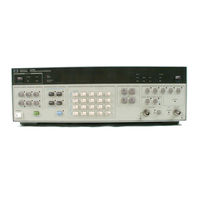
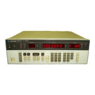
HP 8656A Operating And Service Manual (557 pages)
Signal generator 0.1-990 MHz
Brand:
HP
| Category:
Inverter
| Size: 34.25 MB
Table of Contents
Contents
4
General Information
12
Specifications
12
Safety Considerations
12
Instruments Covered
12
Description
13
Carrier Frequency
13
Output Amplitude
13
Modulation Capabilities
13
Hewlett-Packard Interface Bus
14
Electrical Options
14
Mechanical Options
14
Compability
14
Supplemental Characteristics
18
Frequency
18
Output
18
Spectral Purity
18
Recommended Test Equipment
19
Installation
22
Initial Inspection
22
Preparation for Use
22
Power Requirements
22
Power Cables
23
Time Base Selection
23
Line Voltage and Fuse Selection
23
Line Fuse Ratings and Part Numbers
23
HP-IB Address Selection
24
Power Cable and Mains Plug Part Numbers
24
Mating Connectors
25
Operating Environment
25
Bench Operation
25
Rack Mounting
25
Time Base Jumper Location
26
HP-IB Address Switch Location and Settings
26
Interface Bus Connections
27
Storage and Shipment
28
Environment
28
Packaging
28
Operation
29
Operating Characteristics
29
Local Operation
29
Remote Operation
29
General Operating Instructions
30
Operator's Maintenance
30
Power-On Procedure
30
Power-On Sequence
31
Keystroke Sequences
31
Initialized Conditions
31
Carrier Keystroke Sequence
32
Store-Recall-Display-Sequence
33
Setting Carrier Functions
34
Setting Modulation Functions
34
Changing Parameters Values
34
Simplified Front Panel Features
35
Index of Detailed Operating Instructions
37
Detailed Panel Features
38
Display and Remote Features
39
Carrier Features
41
Carrier Keys
41
RF Output Connector
41
Modulation Features
42
Modulation Keys
42
Source Keys
42
MOD Input/Output Connector
42
Data Entry Keys
43
Units Entry Keys
43
Store-Recall-Display-Sequence Keys
44
INCR SET Key
44
RESET/STBY/ON Switch
45
Rear Panel Features
46
Operator's Checks
47
Basic Functional Checks
47
Frequently Check
48
Output Level Checks
49
FM Check
50
FM Function Check Waveform
50
HP-IB Functional Checks
51
AM Check
51
Address Recognition
52
Remote and Local Messages and the LOCAL Key
53
Data Message
53
Local Lockout and Clear Lockout/Set Local Message
54
Clear Message
55
Abort Message
55
HP-IB Compability
57
HP-IB Message Reference Table
58
Addressing
59
Data Messages
59
Receiving the Data Message
59
Valid Decimal Values Vs. Equivalent ASCII Characters
59
Keyboard-To-Program Code Correlation
60
Value-Selectable Parameters
60
Data Message Examples
60
Sending the Data Message
61
Receiving the Trigger Message
61
Receiving the Clear Message
61
Receiving the Remote Message
61
Receiving the Clear Lockout/Set Local Message
62
Receiving the Pass Control Message
62
Receiving the Abort Message
62
Switching Characteristics
62
Frequency Switching
63
HP-IB Program Codes
63
Commonly Used Code Conversions
64
Amplitude Switching
65
Modulation Switching
65
Frequency Switching Characteristics
65
Amplitude
66
Amplitude Conversion
68
Amplitude, Up/Down
70
Display
71
Display Sequence
72
Frequency, Coarse and Fine Tune
75
Frequency, Up/Down
77
HP-IB Address Display
78
Increment Value Change
80
Increment Value Display
82
Modulation, am
83
Modulation, am Up/Down
84
Modulation, External Source
85
Modulation, FM
86
Modulation, FM Up/Down
88
Modulation, Mixed
89
Modulation, off
93
Recall
95
Sequence
96
Store
97
Performance Tests
98
Equipment Required
98
Performance Test Record
98
Calibration Cycle
98
Spectral Purity Tests
100
High Level Accuracy and Flatness Tests
105
Low Level Accuracy Tests
108
Modulation Tests
110
Adjustments
124
Factory-Selected Components
124
Post-Repair Adjustment
125
Related Adjustments
125
Power Supply Voltage Adjustment
126
Reference Voltage Adjustment
127
Audio Oscillator Level Adjustment
128
AM Offset Adjustment
129
715 Mhz Sideband Adjustment
130
Notch Filter Adjustments
131
High Frequency Loop Offset Adjustment
134
50 Mhz Reference Oscillator Frequency Adjustment
136
50Mhz Reference Oscillator Level Adjustment
137
60 To 110 Mhz Oscillator Flatness Adjustment
138
690 To 740 Mhz if Compensation Adjustment
139
400 Mhz Bandpass Filter Adjustment
140
Level and ALC Loop Detector Adjustments
141
Heterodyne Band Accuracy and Flatness Adjustments
143
AM% and ALC Loop am Adjustments
145
FM Deviation Adjustment
147
FM Frequency Response Adjustment
148
Attenuator Adjustments
149
Option 001 10 Mhz Reference Oscillator Frequency Adjustment
152
Replaceable Parts
153
Abbreviations
153
Factory Selected Parts
153
Parts List Backdating
153
Recommended Spares List
154
Reference Designations
155
Cabinet, Parts Identification
187
Front Panel, Parts Identification
188
Rear Panel, Parts Identification
189
Top Internal View, Top Cover Removed
190
Top Internal View, A3 Assembly in Service Position
191
Bottom Internal View, A10/A11 Assemblies in Service Position
192
Bottom Internal View, Bottom Cover Removed
193
Low Frequency Loop Assembly - A3, Parts Identification
194
Attenuator Assembly - A9, Parts Identification
195
Manual Changes
196
Manual Change Instructions
198
Address Buffering/Decoding, Serial I/O and Control Schematic Diagram
200
Instrument Modifications
205
Improving Power Supply Reliability
205
Decreasing Spurios Signal Output
205
Improving Low Level Accuracy
205
Improving RF Frequency
206
Loss of Signal Generator Control by the Keyboard
206
Service
207
Recommended Test Equipment and Accessories
208
Service Tools, Aids and Information
208
Troubleshooting
209
Assembly Locations
209
Parts and Cable Locations
209
Test Points and Adjustment Locations
209
Strategy
210
Circuit Troubleshooting
210
Signature Analysis
210
Repairs
211
Assembly Access Information
212
A3 Assembly Service Position
212
Level 2 Access
212
Rear Panel and Fan Shroud Removal
213
A10/A11 Assemblies Service Position
213
Level 3 Access
213
Replacement of Key Cap and Pushbutton Switches
214
Fan Shroud Removal
214
Key Cap Replacement
214
Switch Replacement
214
Pushbutton Switch Support Anvi
215
Heat Staking Tip
215
Typical Assembly for Heat Staking Operation
215
Manual Backdating
216
Manual Updating
216
Etched Circuits
216
Schematic Symbology and Operating Principles
216
Etched Circuit Soldering Equipment
217
Gates and Qualifiers
217
Indicator Symbols
217
Contiguous Blocks
217
Basic Logic Symbols and Qualifiers
218
Active Levels
219
Edge Sensitive Inputs
219
Delayed Output Response
219
Inhibit Inputs
219
AND Dependency Notation
220
Address Dependency Notation
221
OR and Free Dependency Notation
221
Common Control Block
221
Complex Device Symbology
222
Shift Register
222
Up/Down Counter
222
Quad D-Type Latch
222
Complex Logic Symbology and Operating Principles
223
Microprocessor
223
Random Access Memory
223
Read Only Memory
223
Multiple Bus Transceivers
224
General Purpose Interface Adapter
224
Successive Approximation Register (SAR)
225
Digital-To-Analog Converter
225
Programmable Interval Timer
226
BCD-To-Seven-Segment Latch/Decoder/Divider
226
Linear Device Operating Principles
227
Operational Amplifiers
227
Comparators
228
Schematic Diagram Notes
229
Low Frequency and FM Section
237
Microprocessor, Keyboard, and Display Section
237
Line Check
238
Power-Up Check
238
Frequency and Amplitude
239
Modulation
239
High Frequency and Output Section
243
Frequency Multiplier Assembly
243
High Frequency Loop Assembly
243
High Frequency Oscillator Assembly
244
Output Assembly
244
Attenuator Assembly
245
Audio/Power Supply Assembly
245
RF Output and Attenuator Check
246
Output Assembly Check
246
Frequency Multiplier
247
Audio/Power Supply
247
Low Frequency Loop Assembly
252
50 Mhz Reference Oscillator Checks
254
Divider Circuit Checks
254
VCO Tune Voltage and FM Checks
255
Frequency Modulation Checks
255
Keyboard Assembly
259
Microprocessor, Memory and HP-IB Assembly
259
Display Assembly
260
Power-On or Reset Sequence
260
Keyboard and HP-IB Checks
261
A4 High Frequency Loop Assembly
266
Voltage Controlled Oscillator
266
Buffer Amplifier
266
Power Splitter
267
IF Buffer Amplifier
268
Sampling Bridge and Pulse Generator
268
Loop and if Sideband Frequencies
269
RF Output Versus HF Loop Output
269
Voltage Tuned Oscillator Check
270
IF Input Filter
271
Notch Filters
271
Pulse Generator, Sampling Bridge
271
P/O A4 High Frequency Loop Assembly
280
Sideband Comparators
281
Gain Compensation
282
HF Loop Data Storage/Drivers
282
Exclusive-Or Gate A4U6
282
Search Amplifier, Loop Amplifier, Sideband Comparator/Sideband Switch
283
High Frequency Loop Signatures
285
A8 Frequency Multiplier Assembly
290
Multiplier Stages Bias Voltages
291
RF Levels
291
RF Diviers
300
ALC Loop
301
Detector Bias
301
ALC Amplifier
301
Output Amplifier
302
PIN Modulator
303
Voltage-Tuned Filters
303
ALC Amplifier Voltage Levels
305
Band Select Shift Register Signatures
313
Voltage Tuned Filter TUNE Voltages
314
Waveforms with HF Loop Unlocked
314
External Modulation
325
P/O Modulation Control Latches, Level DAC
325
P/O Modulation Control Latches, AM% DAC
325
Internal FM Select
326
Internal Modulation
326
External am Select
326
External FM Select
326
RF Amplitude Ranges
327
Amplitude Control
328
Modulation Control
328
Function Control Voltage Levels
329
Attenuator Control
342
Attenuator Control Component Locations
343
Reverse Power Protection Component Locations
344
Attenuator, Attenuator Control/Reverse Power Protection Block Diagrams
345
Linear Amplifier
352
110 Mhz Low-Pass Filter
352
Phase-To-Charge Converter, Charge-To-Voltage Converter
376
Slew Rate Control
377
Summary
377
Tune Sample Control
378
Phase Detector Reset Control
378
Low Slew Rate Mode
388
Data Entry During FM Calibration
388
Low Offset Comparator Circuits
388
U11B Pre-Cal Setting Monostable Operation
389
U11A Start Conversion Monostable Operation
389
U5A Operation
389
High Slew Rate Mode
390
U28B Operation
390
U21B High Slew Rate Monostable Operation
390
FM Calibration Simplified Block Diagram
391
SAR Clock Generator, Successive Approximation Register
392
Low Offset Comparator Control, Low Offset Comparator
393
FM Cal DAC, Current-To-Voltage Converter
393
LF Loop FM System Calibrator Component Locations
394
LF Loop FM System Calibrator Block Diagrams
395
FM Integrator Bias Loop
399
FM Calibration, FM Integrator Sample and Hold Buffer
400
FM Deviation Amplifier
401
FM Deviation Circuits
404
LF Loop FM System Control Component Locations
405
Crystal Phase Lock Circuit
414
Crystal Phase Lock Circuit Voltages
414
Divided Time Base Signals
414
50 Mhz Reference Oscillator
416
Time Base Divider
416
Reference Oscillator and Phase Lock Loop Block Diagrams
417
Restart Circuitry
423
Maskable Interrupt Request
424
Data Bus Buffering
424
System Clock
425
RAM Enable
425
Standby
425
Halt
425
Microprocessor/Memory/Hp-IB Assembly
426
Data Bus
426
Read/Write Control
426
Address Bus
426
Data Bus Verification
427
Microprocessor Data Bus Signatures
428
A7 Assembly Interrupt Input Component Locations
428
Microprocessor, Interrupt Processing and Restart Component Locations
429
Advertisement
HP 8656A Operating Manual (214 pages)
Synthesizer/Function Generator Operating Manual
Brand:
HP
| Category:
Synthesizer
| Size: 7.19 MB
Advertisement
Related Products
HP 8655A
HP HP 8642A/B
HP 8614A
HP HP 8673D
HP 8642A
HP 8642B
HP 8671B
HP 8690B
HP 8672a
HP 8601A
HP Categories
Desktop
Laptop
Server
Monitor
Switch
More HP Manuals
Login
Sign In
OR
Sign in with Facebook
Sign in with Google
Upload manual
Upload from disk
Upload from URL