Sign In
Upload
Manuals
Brands
jcb Manuals
Front End Loaders
210S
jcb 210S Manuals
Manuals and User Guides for jcb 210S. We have
1
jcb 210S manual available for free PDF download: Service Manual
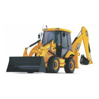
jcb 210S Service Manual (414 pages)
Backhoe Loader
Brand:
jcb
| Category:
Front End Loaders
| Size: 6.98 MB
Table of Contents
Section 1 General Information Section 1
4
Table of Contents
4
Machine Identification Plate
5
Typical Machine Identification Number
5
Typical Engine Identification Number
5
Unit Identification
6
Torque Settings
7
Service Tools Numerical List
8
Service Tools
10
Section 3 Routine Maintenance
31
Service Requirements
34
Introduction
34
Maintenance
34
Owner/Operator Support
34
Service/Maintenance Agreements
34
Lifting Regulations - Inspections and Tests
34
Lubricants - Health and Safety
35
Hygiene
35
Storage
35
Handling
35
First Aid - Oil
35
Spillage
35
Fires
35
Waste Disposal
35
Service Schedules
36
Loader Arm Safety Strut
39
Checking for Damage
40
Cleaning the Machine
40
Seat Belt
41
Checking the Seat Belt Condition and Security
41
ROPS/FOPS Structure
42
Checking the ROPS/FOPS Structure
42
Checking the Fire Extinguisher
42
Engine Panels
43
Removing and Fitting a Side Panel
43
Opening and Closing the Bonnet
43
Grease (Daily)
44
Loader Arms - Standard
45
Backhoe
46
6-In-1 Clamshovel (if Fitted)
47
Backhoe Quickhitch - Mechanical
47
Backhoe Quickhitch - Hydraulic
47
Greasing
48
Axles
48
Propshafts
49
Airmaster Driveshaft
49
Stabiliser Legs
50
Extending Dipper
50
Lubrication
51
Control Levers
51
Hinges
51
Tyres and Wheels
52
Tyre Inflation
52
Checking the Roadwheel Tightness
52
Engine Air Filter
53
Cleaning the Pre-Cleaner
53
Changing the Elements
54
Engine Oil and Filter
55
Checking the Oil Level
55
Changing the Oil and Filter
55
Engine Cooling System
56
Adjusting the Fan Belt
56
Checking the Coolant Level
56
Changing the Coolant
57
Fuel System
58
Types of Fuel
58
Fuel Standards
58
Low Temperature Fuels
58
Fatty Acid Methyl Ester Fuels
58
Petrol
58
Filling the Tank
58
Draining the Filter
59
Changing the Filter Element
59
Draining the Sediment Bowl
60
Bleed the System
60
Syncro Shuttle Transmission
61
Checking the Oil Level
61
Changing the Oil and Filter
61
Brakes
62
Parking Brake Adjustment
62
Checking the Foot Brake Fluid Level
62
Axles
63
Checking the Differential Oil Level
63
Changing the Differential Oil
63
Checking the Hub Oil Levels
64
Changing the Hub Oil
64
Hydraulic System
65
Checking the Fluid Level
65
Changing the Filter Element
66
Electrical System
67
Link Box Fuses
68
Battery
69
Warning Symbols
69
First Aid - Electrolyte
70
Checking the Electrolyte Level
70
Cab Heater
71
Changing the Recirculation Filter
71
Windscreen Washer
72
Stabiliser Legs
73
Wear Pads
73
Wear Pad Adjustment
73
Align Road Wheels
74
Fluids, Lubricants, Capacities and Specifications
75
Coolant Mixtures
76
Section a Attachments Section a
77
Service Tools
79
Hydraulic Tool Circuit (H.T.C.) Attachment
80
Schematic Circuit
80
Circuit Description
81
Flow Diverter Valve
82
Removal and Replacement
82
Dismantling and Assembly
83
Flow Testing
85
Pressure Testing
85
Airmaster Compressor Attachment
86
Care & Safety
86
Unit Identification
88
Safety Decals
89
Routine Maintenance
90
Compressor Approved Oils
90
Service Schedules
90
Compressed Air Filter - Changing the Elements
91
Compressor Oil and Filter - Draining Air Receiver Condensate
92
Changing Oil and Filter
93
Safety Valve
95
Checking Safety Valve Operation
95
Oil Cooler
97
Technical Data
97
Basic Operation
99
General Description
99
Compressor Unit
99
Compression Cycle
99
Lubrication System
100
Cooling System
100
Oil Separation and Recovery
101
Unloading and Speed Control
103
Blow down Valve
104
Transmission
105
Fault Finding
106
Commissioning the Compressor
108
Air/Oil Separator Removal and Replacement
109
Pressure Regulator
110
Off-Load Air Pressure Regulation
110
Checking Safety Valve Setting
110
Suction Unloader Dismantling
111
Assembly
115
Compressor Unit
115
Dismantling
115
Assembly
117
Section B Body & Framework Section B
119
Service Tools
120
Basic Operation
123
Air Conditioning
123
R-134A Refrigerant
123
System Operation
123
System Control
124
Fault Finding
125
Air Conditioning
125
General Fault Indications
125
Wiring Continuity Checks
127
Service Procedures
128
Air Conditioning
128
Leak Testing
128
Tightening Leaking Hoses
128
Checking Refrigerant Charge Level
128
Pressure Switch Testing
129
Condenser Coil Cleaning
130
Filters - Changing and Cleaning
131
Compressor Drive Belt - Adjusting
132
Glazing
133
Removing Broken Glass and Old Sealant
133
Cab ROPS/FOPS Structure - Checks
138
Stabiliser Leg - Wear Pad Adjustment
139
Air Conditioning
140
Compressor Clutch Relay
140
Removal and Replacement
165
Stabiliser Leg
168
Removal and Replacement
168
Section E Hydraulics Section E
170
Introduction to Hydraulic Schematic Symbols
180
Circuit Schematic
187
Circuit Descriptions
194
Hydraulic Pump Operation
194
Loader Valve
201
Arms Lower
201
Float
201
Excavator Valve Neutral Circuit
206
Pilot Operated Pressure Relief Valve Operation
214
Smooth Ride System
220
Fault Finding
220
Smooth Ride System
224
Service Procedures
225
Hydraulic Contamination
225
Flow and Pressure Testing
226
Pressure Testing
228
Quick Release Couplings
230
Smooth Ride System
231
Charging/Discharging the Accumulator
231
Main Pump
232
Removal and Replacement
237
Auxiliary Pump (if Fitted)
237
Removal and Replacement
240
Loader Valve
240
Dismantling and Assembly
241
Standard Spool
245
Float Spool
247
Excavator Valve
249
Removal and Replacement
249
Dismantling and Assembly
252
Hydraclamp Valve
256
Typical Ram
258
JCB Ram Sealing Procedure
260
Smooth Ride System
262
Accumulator Removal and Replacement
262
Section F Transmission Section F
265
Service Tools
267
Axles
267
Syncro Shuttle Gearbox
270
Technical Data
271
Basic Operation
275
Systems Description
281
Synchromesh - Operation
282
Fault Finding
285
Syncro Shuttle Gearbox - Hydraulic
285
Mechanical
286
Pto
290
Service Procedures
291
Front and Rear Axle - Renewing the Pinion Oil Seal
291
Brakes - Testing for Piston Seal Leakage
292
Pressure and Flow Tests
294
Solenoid Valve
296
Dismantling and Assembly
296
Torque Converter Stall Test
297
Removing and Replacing
298
Front Axle
299
Removal and Replacement
300
Drive Head Maxtrac
305
Pinion Depth Setting
307
Collapsible Spacer Assembly
308
Crownwheel and Pinion Meshing
309
Syncro Shuttle Gearbox
336
Shaft End Float Measurements
344
Reverser Unit
348
Power Take off Clutch (if Applicable)
353
Piston Ring Seals - Fitting Procedure
357
Torque Converter
358
Section G Brakes Section G
359
Technical Data
361
Basic System Operation
361
Pedals Locked - Normal Operation
361
Pedals Locked - Compensating Operation
361
Pedals Unlocked - Normal Operation
361
Fault Finding
362
Service Procedures
365
Service Brakes
365
Brake Piston Seal Leakage Test
365
Parking Brake
366
Testing
367
Adjustment
367
Compensating Master Cylinder
369
Removal and Replacement
370
Dismantling and Assembly
371
Service Brakes
372
Dismantling and Assembly
372
Bleeding
373
Parking Brake
374
Torque Figures
374
Calliper Removal and Replacement
375
Calliper Dismantling and Assembly
377
Section H Steering Section H
380
Service Tools
381
Technical Data
382
System Type
382
Basic System Operation
383
Steer System Schematics
383
Hydraulic Operation
384
Circuit Description
385
Fault Finding
399
Service Procedures
402
Initial System Bleeding
402
Re-Aligning the Road Wheels
404
Steer Rams
405
Removal and Replacement
406
Dismantling and Assembly
406
Priority Valve
406
Bleeding
406
Hydraulic Steer Unit
407
Dismantling and Assembly
409
Advertisement
Advertisement
Related Products
jcb 2CX
jcb 2CXU
jcb 210SU
jcb 205T
jcb 210 Series
jcb 210LC
jcb 210SC
jcb 210NLC
jcb 210SLC
jcb 210X
jcb Categories
Excavators
Compact Loader
Power Tool
Construction Equipment
Drill
More jcb Manuals
Login
Sign In
OR
Sign in with Facebook
Sign in with Google
Upload manual
Upload from disk
Upload from URL