Sign In
Upload
Manuals
Brands
Kenwood Manuals
Transceiver
S-811B
Kenwood S-811B Manuals
Manuals and User Guides for Kenwood S-811B. We have
1
Kenwood S-811B manual available for free PDF download: Service Manual
Kenwood S-811B Service Manual (115 pages)
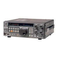
144Hz/430MHz All mode transceiver
Brand:
Kenwood
| Category:
Transceiver
| Size: 14.95 MB
Table of Contents
Contents
1
Circuit Description
2
Frequency Configuration
2
RF Unit
3
Frequency-Related Block Diagram
3
IF Unit
4
RX Section Diagram
4
TX Section Diagram
4
Transmission System
5
Power Control Configuration
5
ND487C1-3R Electric Characteristic (if Unit D16)
5
AF Unit
6
Final Unit
6
AVR Unit
6
PLL Unit
6
HET Unit
7
PLL, HET Unit Block Diagram
8
Digital Control Block Diagram
9
Schematic Diagram
11
Control Unit
14
Key Switch Section
15
Display/Mode Control Section
15
Keyboard Ass'y Schematic Diagram
15
Mode Switching Circuit
15
DCS System Control Section
16
DCS System Block Diagram
17
Reset and Backup
18
DCS System Flow Chart
18
Modem Block Diagram
18
Reset Circuit and Waveform at Respective Points
18
"Beep" Tone Oscillator and Voice Synthesis Control Section
19
Encoder Section
19
Other I/O Sections
20
Output Waveform of Main Encoder
20
STBY Output Circuit
20
Encoder Ass'y
21
Waveforms at 4 and 9 I/O Pins with Harness Connected
21
Relationship between Plunger Drive Pulse and Sensor
21
Display Unit
22
Parts List
23
Capacitors List
23
Semiconductor List
24
Encoder Ass'y Parts List
24
General Parts List
25
Switch Unit Parts List
26
AVR Unit Parts List
27
RF Unit Parts List
27
Final Unit Parts List
28
IF Unit Parts List
28
AF Unit Parts List
30
PLL Unit Parts List
30
Tone Unit Parts List
32
Control Unit Parts List
32
Display Unit Parts List
33
HET Unit Parts List
42
PC Boards Views
45
Switch Unit PC Board
45
Tone Unit PC Board
45
AVR Unit PC Board
46
RF Unit PC Board
47
Final Unit PC Board
48
AF Unit PC Board
49
Display Unit PC Board
50
Keyboard Ass'y PC Board
51
Disassembly
53
Adjustment
57
Required Test Equipment
57
TX/RX Section Adjustments
58
A/E RX Section Adjustments
59
A/E TX Section Adjustments
60
A/E Encoder Section Adjustments
62
Top View
63
Bottom View
64
TX/RX Section (Common) Adjustments
65
A/B/E RX Section Adjustments
67
A/B/E TX Section Adjustments
68
Encoder Section Adjustments
70
Microprocessor Operation Check
73
DSC (Digital Code Squelch) System Operation Check
74
Level Diagram
75
Packing
77
Terminal Function
78
PC Boards View
82
Circuit Diagram
84
IF Unit Circuit Diagram
85
PLL Unit Circuit Diagram
86
HET Unit Circuit Diagram
90
Control Unit Circuit Diagram
91
Display Unit Circuit Diagram
93
Block Diagram
97
CD-10 (Call Sign Display) Parts List
106
CD-10 (Call Sign Display) Schematic Diagram
107
CD-10 (Call Sign Display) PC Board View
108
Reference Data
109
AC-10 Specifications/Schematic Diagram
111
TU-5 Schematic Diagram/Pc Board View
111
VS-1 - Voice Synthesizer Parts List
112
VS-1 - Voice Synthesizer Schematic Diagram
112
Specifications
113
Advertisement
Advertisement
Related Products
Kenwood S-811E
Kenwood SC-8
Kenwood SC-8T
Kenwood SP-930
Kenwood S0-1
Kenwood SO-1
Kenwood SP-120
Kenwood SP-430
Kenwood SP-S30
Kenwood SP-71
Kenwood Categories
Car Receiver
Transceiver
CD Player
Amplifier
Receiver
More Kenwood Manuals
Login
Sign In
OR
Sign in with Facebook
Sign in with Google
Upload manual
Upload from disk
Upload from URL