Sign In
Upload
Manuals
Brands
Kenwood Manuals
Transceiver
TS-480SAT
Kenwood TS-480SAT Manuals
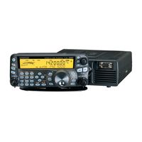
Manuals and User Guides for Kenwood TS-480SAT. We have
6
Kenwood TS-480SAT manuals available for free PDF download: Service Manual, Instruction Manual, User Manual, Setting Manual, Reference Manual
Kenwood TS-480SAT Instruction Manual (106 pages)
HF/ 50 MHz ALL MODE TRANSCEIVER
Brand:
Kenwood
| Category:
Transceiver
| Size: 6.04 MB
Table of Contents
Instruction Manual
1
Before Starting
2
Thank You
3
Features
3
Supplied Accessories
3
Models Covered by this Manual
4
Market Codes
4
Writing Conventions Followed
4
Precautions
5
Table of Contents
6
Contents
7
Chapter 1 Installation
9
Mobile Installation
9
Installation Example
9
Remote Control Panel Installation
9
DC Power Cable Connection
10
Antenna Connection
10
Ignition Noise
10
Fixed Station Installation
11
Remote Control Panel Installation
11
DC Power Supply Connection
11
Antenna Connection
12
Ground Connection
12
Lightning Protection
12
Portable Bracket (E-Type Only)
13
Fuses
13
Panel and Microphone Connection
14
Panel and Microphone Connection Using Pg-4Z (Option)
14
Accessory Connections Tx/ Rx Unit
15
Micropohone (MIC)
15
External Speaker (EXT.SP)
15
Keys for CW (PADDLE and KEY)
15
Remote Control Panel
15
Headphones (PHONES)
15
Chapter 2 Your First Qso
16
Reception
16
Transmission
17
Chapter 3 Getting Acquainted
18
Remote Control Panel
18
Lcd Display
21
Tx/ Rx Unit
23
Remote Control Panel (Rear)
25
Microphone
25
Chapter 4 Operating Basics
26
Switching Power On/Off
26
Adjusting Volume
26
Af (Audio Frequency) Gain
26
Rf (Radio Frequency) Gain
26
Selecting Vfo a or Vfo B
26
Selecting a Band
27
Selecting a Mode
27
Adjusting Squelch
27
Selecting a Frequency
27
Multi-Function Meter
28
Transmitting
28
Selecting Transmission Power
28
Microphone Gain
29
Chapter 5 Menu Setup
30
What Is a Menu
30
Menu A/ Menu B
30
Menu Access
30
Quick Menu
30
Programming the Quick Menu
30
Using the Quick Menu
30
Menu Configuration
31
Alphabetical Function List
34
Chapter 6 Basic Communications
35
Ssb Transmission
35
Fm Transmission
35
Am Transmission
36
Narrow Bandwidth for Fm
36
Narrow Bandwidth for am
36
Cw Transmission
37
Auto Zero-Beat
37
Tx Sidetone/ Rx Pitch Frequency
37
Chapter 7 Enhanced Communications
38
Split-Frequency Operation
38
Tf-Set
38
(Transmission Frequency Set)
38
Fm Repeater Operation
39
Transmitting a Tone
40
Activating the Tone Function
40
Selecting a Tone Frequency
40
Tone Freq. ID Scan
40
Fm Ctcss Operation
41
Ctcss Freq. ID Scan
41
Chapter 8 Communicating Aids
42
Reception
42
Selecting Your Frequency
42
Direct Frequency Entry
42
Using the Mhz Key
42
Quick QSY
42
Configuring the Tuning Control as MULTI Control (FM)
42
Fine Tuning
43
Tuning Control Adjustment Rate
43
Equalizing VFO Frequencies (A=B)
43
Rit (Receive Incremental Tuning)
43
Agc (Automatic Gain Control)
43
Transmission
44
Vox (Voice-Operated Transmit)
44
Microphone Input Level
44
Delay Time
44
Anti-VOX Adjustment
44
VOX Source
44
Speech Processor
45
Xit (Transmit Incremental Tuning)
45
Customizing Transmission Signal Characteristics
46
TX Filter Bandwidth (SSB/ AM)
46
TX Equalizer (SSB/ FM/ AM)
46
Transmit Inhibit
46
Busy Lockout
46
Changing Frequency While Transmitting
46
Cw Break-In
47
Using Semi Break-In or Full Break-In
47
Electronic Keyer
47
Changing Keying Speed
47
Auto Weighting
47
Reverse Keying Weight Ratio
47
Bug Key Function
48
Cw Message Memory
48
Storing CW Messages
48
Checking CW Messages Without Transmitting
48
Transmitting CW Messages
48
Changing the Inter-Message Interval Time
49
Changing the Sidetone Volume
49
Inset Keying
49
Frequency Correction for Cw
49
Auto Cw Tx in Ssb Mode
49
MIC Up/ Dwn Key Paddle Mode
49
Swap Dot and Dash Paddle Postion
49
Chapter 9 Specialized Communications
50
Radio Teletype (Rtty)
50
AMTOR/ Pactor/ CLOVER/ G-TOR/ PSK31
51
Packet Radio
51
Slow Scan Tv/ Facsimile
52
Chapter 10 Rejecting Interference
53
If Filter
53
Changing the if Filter Bandwidth
53
Ssb/ am
53
Cw/ Fsk
53
If Shift (Ssb/ Cw/ Fsk)
53
Dsp Filters
54
Changing the Dsp Filter Bandwidth
54
Ssb/ Fm/ am
54
Cw/ Fsk
54
Beat Cancel (Ssb/ Fm/ Am)
55
Noise Reduction (All Modes)
55
Setting the NR1 Level Adjustment
55
Settign the NR2 Time Constant
55
Noise Blanker
55
Digital Noise Limiter (Dnl)
55
Dsp Filter for Data Communication (Ssb/ Fm)
56
Dsp Rx Monitor
56
Pre-Amplifier
57
Attenuator
57
Cw Reverse
57
Chapter 11 Memory Features
58
Memory Channels
58
Storing Data in Memory
58
Simplex Channels
58
Split-Frequency Channels
59
Memory Recall and Scroll
59
Memory Recall
59
Memory Scroll
60
Temporary Frequency Changes
60
Memory Transfer
60
Memory \ VFO Transfer
60
Channel \ Channel Transfer
60
Storing Frequency Ranges
61
Confirming Start/End Frequencies
61
Programmable VFO
62
Memory Channel Lockout
62
Erasing Memory Channels
62
Memory Channel Name
62
Quick Memory
63
Storing into Quick Memory
63
Recalling Quick Memory Channels
63
Temporary Frequency Changes
63
Quick Memory ➡ Vfo Transfer
63
Chapter 12 Scan
64
Normal Scan
64
Vfo Scan
64
Program Scan
64
Program Scan Partially Slowed
65
Scan Hold
65
Memory Scan
66
Scan Resume Method
66
All-Channel Scan
66
Group Scan
67
Memory Group
67
Scan Group Select
67
Performing Group Scan
67
Chapter 13 Operator Conveniences
68
Antennas
68
APO (Auto Power OFF)
68
Automatic Antenna Tuner
68
Presetting
69
External Antenna Tuner Type
69
Attenuator
69
Auto Mode
69
Beep Function
70
Display
71
Brightness
71
Key Illumination
71
Linear Amplifier Control
71
Lock Functions
71
Frequency Lock Function
71
Tuning Control Lock Function
71
Microphone Pf Keys
72
Pf Key
72
Rx Dsp Equalizer
72
Equalizing Receiving Audio
72
Rx Monitor
72
Time-Out Timer
73
Transverter
73
Frequency Display
73
Transmission Output Power
73
Tx Monitor
73
Tx Power
73
Tx Tune
74
Transferring Data
74
Receiving Data
74
Quick Data Transfer
75
Setting up
75
Equipment Needed
75
Connections
75
Using Quick Transfer
75
Computer Control
75
Communication Parameters
75
Controlling the Ts-480 from Pc
76
Remote Controlling the Ts-480 on the Network
76
Voice Guide and Storage Unit (Optional)
76
Recording Messages
76
Message Playback
77
Checking Messages
77
Sending Messages
77
Erasing a Recorded Message
77
Changing Inter-Message Interval Time
77
Changing Playback Volume
77
Constant Recording
77
Voice Guide
78
Voice Guide Announcement Volume
79
Voice Guide Announcement Speed
79
DX Packetcluster Tune
80
Sky Command II (K-Type Only)
81
Sky Command II Diagram
81
Preparation
81
Control Operation
81
Using the Th-D7A as a Commander
82
Control Operation
82
Chapter 14 Connecting Peripheral Equipment
84
Computer
84
Compatible Transceiver
84
Rtty Operation
85
HF/ 50 Mhz LINEAR AMPLIFIER
85
Antenna Tuner
86
Mcp and Tnc
86
DX Packetcluster Tune
87
Crossband Repeater
87
Sky Command II (K-Type Only)
88
Chapter 15 Installing Options
89
Removing the Top Cover
89
Voice Guide and Storage Unit
89
Yf-107C/ Cn/ Sn if Filters and So-3 Tcxo
89
Reference Frequency Calibration
90
Chapter 16 Troubleshooting
91
General Information
91
Service
91
Service Note
91
Cleaning
91
Backup Battery
91
Troubleshooting
92
Microprocessor Reset
96
Initial Settings
96
Partial Reset
96
Full Reset
96
Demonstration Mode
96
Operation Notices
97
DC Power Supply
97
Fan Noises
97
Internal Beats
97
Agc
97
60 M BAND OPERATION (K-TYPE/ USA ONLY)
97
Chapter 17 Optional Accessories
98
Optional Accessories
98
Chapter 18 Specifications
99
Specifications
99
Chapter 19 Index
101
Advertisement
Kenwood TS-480SAT Service Manual (143 pages)
HF/50MHz All mode transceiver
Brand:
Kenwood
| Category:
Transceiver
| Size: 37.6 MB
Table of Contents
Contents
1
Product View
1
Disassembly for Repair
2
How to Remove the Torque Changeover Lever (G02-0898-04)
2
How to Mount the Torque Changeover Lever (G02-0898-04)
2
Cautions for Mounting the Main Dial Knob (K21-1105-03)
2
Circuit Description
3
Frequency Configuration
3
Reference Signal Generator
3
Lo1/Lo2/Car
3
CAR (Carrier)
4
LO1 Frequency Shift Data
4
Receiver Circuit
5
From Antenna to a Preamplifier (Q153, 154)
5
CAR Frequency Shift Data
5
Rf Bpf
5
From Receiving 1St Mixer to the Second if Frequency (10.695Mhz)
6
10.695Mhz if Filter Circuit (Filter Section (X57-663 B/2) of the TX-RX Unit
6
From Antenna to the Second if Frequency (10.695Mhz)
6
IF Filter Selection
6
From the Receiver Second if to Detection (TX-RX Unit (X57-663 A/2))
7
10.695Mhz if Filter Circuit
7
From the Receiver Second if to Detection
7
Transmitter Circuit
8
Signal Path Before/ after the CODEC
8
From Detection to AF Output
8
From the MIC Terminal to Modulation Output
8
Modulation Circuit
9
Constant Received Audio Recording Function
9
Other Functions
9
From the Modulation Circuit to 10.695Mhz
10
From 10.695Mhz to the Drive Output
10
FM Mode
10
FM Mode Modulation Circuit
10
From the Drive Output to Antenna
11
100W Transceiver
11
200W Transceiver
11
From the Drive Output to Antenna (100W)
11
Common Functions between 100W and 200W
12
ALC Circuit and Transmission Power Control
12
From the Drive Output to Antenna (200W)
12
From the Drive Output to Antenna (100W and 200W Common Functions)
12
Digital Control Circuit
13
Outline
13
Around the Main Microcomputer
13
Around the DSP
13
Components Description
14
RF Unit (X44-327X-XX)
14
Final Unit (X45-365X-XX) (A/3)
15
Final Unit (X45-365X-XX) (B/3)
15
Final Unit (X45-365X-XX) (C/3)
15
Final Unit (X57-366X-XX) (A/3)
15
Final Unit (X45-366X-XX) (B/3)
16
Final Unit (X45-366X-XX) (C/3)
16
Display Unit (X54-3410-00)
16
TX-RX Unit (X57-663X-XX)
16
TX-RX Unit (X57-663X-XX) (B/2)
19
Sub Unit (X58-4900-XX)
19
Semiconductor Data
20
Main Microcomputer: HD64F2338VFC25 (TX-RX Unit IC204)
20
Panel Microcomputer: 30622M8A-7N0GP (Display Unit IC3)
22
Extended I/O Port
23
RF Unit
23
Final Unit
23
TX-RX Unit
24
Mixer: TC4107F (RF Unit IC251)
25
Mixer: NJM1496V (TX-RX Unit IC621)
25
Baffer: HD74LV541AT (TX-RX Unit IC222)
25
Equivalent Circuit
25
CODEC: AK4550VT (TX-RX Unit IC217)
26
D/A: M62353AGP (TX-RX Unit IC681)
26
Block Diagram
26
Pin Function
26
Parts List
27
Ts-480Hx/480Sat
27
RF Unit (X44-327X-XX) 0-00: KH,KS 2-71: EH,ES
28
Final Unit (X45-365X-XX) 0-11: KS 2-71: es
31
Final Unit (X45-366X-XX) 0-00: KH 2-71: EH
35
Display Unit (X54-3410-00)
38
TX-RX Unit (X57-663X-XX) 0-11: KH 0-12: KS 2-71: EH 2-72: es
39
Sub Unit (X58-4900-XX) -00: KH,EH -01: KS,ES
49
Exploded View (Main Body Upper Side)
50
Exploded View (Main Body Lower Side): TS-480SAT
51
Exploded View (Main Body Lower Side): TS-480HX
52
Exploded View (Panel)
53
Packing
54
Adjustment
55
Required Test Equipment
55
Preparation
56
TX/RX Unit
56
Remote Control Panel
56
Service Jig
56
How to Use the Coaxial Cable and the Flat Cable
57
How to Use the Data Terminal Short Plug
57
DATA Connector Pin Assignment
57
Updating the Firmware
58
Adjustment Mode
58
Adjustment Mode Menu (Menu No. 00~78)
59
Menu No. 77 Checksum Display
60
Display Check
61
PLL Section
61
Receiver Section
62
Transmitter Section (TS-480HX)
66
Transmitter Section (TS-480SAT)
69
Adjustment Points (Upper Side)
73
Adjustment Points (Lower Side): TS-480HX
74
Adjustment Points (Lower Side): TS-480SAT
75
Interconnection Diagram
76
PC Board
78
RF Unit (X44-327X-XX) 0-00: KH,KS 2-71: EH,ES Component Side View (J72-0874-19)
78
RF Unit (X44-327X-XX) 0-00: KH,KS 2-71: EH,ES Foil Side View (J72-0874-19)
80
RF Unit (X44-327X-XX) Schematic Diagram
82
100W Final Unit (X45-365X-XX) (A/3) 0-11: KS 2-71: es Component Side View (J72-0875-09)
86
100W Final Unit (X45-365X-XX) (A/3) 0-11: KS 2-71: es Foil Side View (J72-0875-09)
88
Final Unit (X45-365X-XX) (A/3) [AT] Schematic Diagram
90
Final Unit (X45-365X-XX) (A/3) Schematic Diagram
91
Final Unit (Filter) (X45-365X-XX) (B/3) [AT] 0-11: TS-480SAT(K) 2-71: TS-480SAT(E) Schematic Diagram
93
100W Final Unit (X45-365X-XX) (B/3) 0-11: KS 2-71: es Component Side View (J72-0875-09)
94
100W Final Unit (X45-365X-XX) (B/3) 0-11: KS 2-71: es Foil Side View (J72-0875-09)
95
100W Final Unit (X45-365X-XX) (C/3) 0-11: KS 2-71: es Component Side View (J72-0875-09)
96
Final Unit (ANT)(X45-365X-XX)(C/3)[AT] 0-11: TS-480SAT(K) 2-71: TS-480SAT(E) Schematic Diagram
97
200W Final Unit (X45-366X-XX) (A/3) 0-00: KH 2-71: EH Component Side View (J72-0876-09)
98
200W Final Unit (X45-366X-XX) (A/3) 0-00: KH 2-71: EH Foil Side View (J72-0876-09)
100
Final Unit (X45-366X-XX)(A/3)[200W] 0-00: TS-480HX(K) 2-71: TS-480HX(E) Schematic Diagram
102
Final Unit (X45-366X-XX) (A/3) Schematic Diagram
103
Final Unit (Filter) (X45-366X-XX)(B/3) [200W] 0-00: TS-480HX(K) 2-71: TS-480HX(E) Schematic Diagram
105
200W Final Unit (X45-366X-XX) (B/3) 0-00: KH 2-71: EH Component Side View (J72-0876-09)
106
200W Final Unit (X45-366X-XX) (B/3) 0-00: KH 2-71: EH Foil Side View (J72-0876-09)
107
200W Final Unit (X45-366X-XX) (C/3) 0-00: KH 2-71: EH Component Side View (J72-0876-09)
108
Final Unit (ANT)(X45-366X-XX)(C/3)[200W] 0-00: TS-480HX(K) 2-71: TS-480HX(E) Schematic Diagram
109
Display Unit (X54-3410-00) (A/3, B/3, C/3) Component Side View (J72-0877-09)
110
Display Unit (X54-3410-00) (A/3, B/3, C/3) Foil Side View (J72-0877-09)
112
Display Unit (X54-3410-00) (A/3) Schematic Diagram
114
TX-RX Unit (X57-663X-XX) (A/2, B/2) 0-11: KH 0-12: KS 2-71: EH 2-72: es Component Side View (J72-0878-19)
116
TX-RX Unit (X57-663X-XX) (A/2, B/2) 0-11: KH 0-12: KS 2-71: EH 2-72: es Foil Side View (J72-0878-19)
118
TX-RX Unit (X57-663X-XX)(A/2) Schematic Diagram
120
TX-RX Unit (RCXO & BPF) (X57-663X-XX)(B/2) 0-11: TS-480HX(K) 0-12: TS-480SAT(K) 2-71: TS-480HX(E) 2-72: TS-480SAT(E) Schematic Diagram
127
Sub Unit (X58-4900-XX) -00: KH,EH -01: KS,ES Component Side View (J72-0888-09)
128
Terminal Function
129
RF Unit (X44-327)
129
Final Unit (X45-365 A/3 & X45-366 A/3)
129
Final (Filter) Unit (X45-365 B/3 & X45-366 B/3)
130
Final (ANT) Unit (X45-365 C/3 & X45-366 C/3)
130
Display Unit (X54-341 A/3)
130
Display (AF/SQL VR) Unit (X54-341 B/3)
131
Display (Multi/If Shift VR) Unit (X54-341 C/3)
131
TX-RX Unit (X57-663 A/2)
131
TX-RX (OP Filter/Tcxo) Unit (X57-663 B/2)
133
Sub Unit (X58-490)
133
Block Diagram
134
Level Diagram (RX Section)
136
Level Diagram (TX Section)
138
Accessories
140
Specifications
141
General
141
Transmitter
141
Receiver
142
Kenwood TS-480SAT Service Manual (158 pages)
HF / 50MHz ALL MODE TRANSCEIVER
Brand:
Kenwood
| Category:
Transceiver
| Size: 6.67 MB
Table of Contents
English
1
Table of Contents
1
Disassembly for Repair
2
Circuit Description
3
Receiver Circuit
5
Components Description
14
Semiconductor Data
20
Parts List
27
Exploded View
50
Packing
54
Adjustment
55
Updating Firmware
58
Adjustment Mode
58
Adjustment Mode Menu
59
Interconnection Diagram
76
Rf Unit (X44-327X-XX)
76
Schematic Diagram
85
Final Unit (X45-365X-XX) (A/3)
91
Final Unit (X45-365X-XX) (B/3)
104
Final Unit (X45-365X-XX) (C/3)
105
Final Unit (X45-366X-XX) (A/3)
106
Final Unit (X45-366X-XX) (B/3)
108
Unknown
109
Final Unit (X45-366X-XX) (C/3)
109
C806
110
L19 C12
110
Q9 6B Q807
110
R823 R804
110
Ref. No. Address
110
Component Side Layer
117
Foil Side
118
Display Unit (X54-3410-00) (A/3, B/3, C/3)
120
Tx-Rx Unit (X57-663X-XX) (A/2, B/2)
129
Sub Unit (X58-4900-XX)
144
Layer 1
118
Terminal Function
145
Block Diagram
150
Level Diagram
152
Accessories
156
Specifications
157
Advertisement
Kenwood TS-480SAT User Manual (60 pages)
TS-480 series
Brand:
Kenwood
| Category:
Transceiver
| Size: 2.37 MB
Table of Contents
Table of Contents
2
Determination to Create a Unique Transceiver
3
Back to Basics: “The Appeal of HF Lies in DX’ing.”
3
Design Objectives
3
Standalone Control Panel
4
Focus on Basic Performance
4
The 200W Challenge
4
Adding Appeal to Fixed Station Operations
5
Overview of the TS-480 Series
5
Achieving 200W Output in a Compact Transceiver
6
The TS-480 Concept Began with Development of the TS-570?
6
Development Objectives for the TS-480 Series
6
Focusing on HF
7
Circuitry
8
TX Circuits
8
200W Final Section
8
TX IMD (Output 200W)
9
TX Spurious Emissions
9
SPS (Separate Power Sources) [TS-480HX Only]
10
SPS Schematic Diagram
10
Failsafe Device (some TS-480HX Versions Only)
11
100W Final Section
11
Antenna Tuner (TS-480SAT)
11
100W Final Section with Antenna Tuner
12
FM Circuit
13
FM Modulation Block Diagram
13
RX Circuitry
14
Front End
14
RX 1St Mixer
14
RX Dynamic Range
15
RX Sensitivity
16
Jumpers for Joy
17
Jumper Locations
17
RF Unit (X44-3270-00) Component Surface (J72-0874-19)
17
Circuitry after the Roofing Filter
18
Comparison of Optional CW Filters (500Hz)
18
Option Installation Unit
19
Full Compatibility with Digital Modes (Data Modes)
20
Features Useful for 50Mhz Operations
20
Features Useful for Mobile Operations
20
Auxiliary Features
20
New 5Mhz Band
21
Ideal for Mobile Operations: DNL
22
Principle of DNL Operation
22
DSP Circuit
22
Features of the Built-In DSP
22
The Effect of DNL on Ignition Noise
23
Noise Reduction
23
Nr off
24
Nr1 on
24
Nr2 on
24
Bc on
25
Beat Cancel
25
Bc off
25
RX DSP Filters
26
Slope Tune in Action
26
Switching WIDTH During CW Operations
27
RX Equalizer & TX Equalizer
28
TX Equalizer Characteristics (Example)
28
CW Auto Tune
28
TS-480 Menus
29
Tips
29
Functions that Can be Assigned to PF Keys
34
Making Menus Easier to Use
36
Menu Switching
36
Quick Menu
36
Internal Structure of the Main Unit
37
Structural Features
37
Cooling
38
Cooling Diagram
38
Temperature Rise Around Final Transistors
40
Temperature Rise of Die-Cast Aluminum Chassis Around GND Terminal on Rear
40
Temperature Rise Measured at Center of the Upper Case of the Main Unit
41
Design Concept
42
Constant Recording Function
43
Message Recording/Playback Function
43
New Option: Voice Guide & Storage Unit (VGS-1)
43
Voice Guide
44
Other Features
45
Button Layout & Basic Operation
46
KNS Added
46
Main Functions
46
New Option: ARCP-480 (Amateur Radio Control Program for TS-480) Freeware
46
New Option: ARCP-480 (Freeware)
46
Changing Memory and Registered Details
47
CW Keying
47
Special Code Input
47
Reading and Writing Files
48
Compatibility with KNS (Kenwood Network Command System)
48
Setting up KNS on the ARCP Side
49
Accidental Continuous TX
49
Using a Broadband Router
51
New Option: ARHP-10 (Amateur Radio Host Program) Freeware
52
Make an Audio/Voice Cable & Connect the TS-480 to Your PC
52
Checking LAN Settings
52
New Option: ARHP-10 (Freeware)
52
Adjust PC Volume
53
User Setup
53
Troubleshooting
55
Sound
57
Kenwood TS-480SAT Setting Manual (26 pages)
Kenwood network command system
Brand:
Kenwood
| Category:
Transceiver
| Size: 0.54 MB
Table of Contents
Table of Contents
2
1 Relevant Models
3
2 Objectives of this Document
3
3 Outline
4
Overall Configuration
4
Outline of Host Station (Transmitter) Operations
5
Host Station (Transmitter) Configuration
6
Outline of Remote Station (Operator) Operations
8
Remote Station (Operator) Configuration
9
4 Settings
11
Connecting a Communications Cable
11
Connecting an Audio Cable
11
Transceiver Settings
13
Setting Transmission Methods for Audio Input to the DATA Connector
14
Setting a Broadband Router
15
Software Installation and Settings
16
Windows Firewall Settings
17
Comprehensive Security Software Settings
17
Making the Host Station Connection Request Wait Mode
17
Connecting to the Host Station from the Remote Station
17
5 Limitations Caution
18
PC Environment Limitations
18
Network Environment Limitations
18
Program Limitations
18
6 Frequently Asked Questions
19
Kenwood TS-480SAT Reference Manual (26 pages)
Brand:
Kenwood
| Category:
Transceiver
| Size: 0.12 MB
Table of Contents
About this Reference
2
Hardware Description
2
Control Operation
2
Computer Control Commands
3
Pc Control Command Tables
4
Advertisement
Related Products
Kenwood TS-480
Kenwood TS-480HX
Kenwood TS-430S
Kenwood TS-440S
Kenwood TS-450S
Kenwood TS-700SP
Kenwood TS-811A
Kenwood TS-900
Kenwood TS-830M
Kenwood TS-940S
Kenwood Categories
Car Receiver
Transceiver
CD Player
Amplifier
Receiver
More Kenwood Manuals
Login
Sign In
OR
Sign in with Facebook
Sign in with Google
Upload manual
Upload from disk
Upload from URL