Sign In
Upload
Manuals
Brands
Motorola Manuals
Single board computers
CompactPCI CPN5365
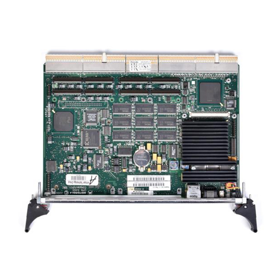
Motorola CompactPCI CPN5365 Manuals
Manuals and User Guides for Motorola CompactPCI CPN5365. We have
1
Motorola CompactPCI CPN5365 manual available for free PDF download: Installation And Use Manual
Motorola CompactPCI CPN5365 Installation And Use Manual (126 pages)
Single Board Computer and CPTM-01 Transition Module
Brand:
Motorola
| Category:
Single board computers
| Size: 3.87 MB
Table of Contents
Table of Contents
8
Comments and Suggestions
20
Conventions Used in this Manual
20
CHAPTER 1 Hardware Preparation and Installation
22
Unpacking Instructions
22
Antistatic Precautions
23
Equipment Required
24
Overview of Startup Procedures
24
Introduction
25
Features
25
Input/Output Interfaces
26
Table 1-1. Input/Output Interfaces on the CPN5365 and the CPTM-01
26
Front Panel Connectors, Switches, and Indicators
27
Figure 1-1. Front Panel Connectors, Reset Switch, and Leds
28
CPN5365 On-Board Components
29
Figure 1-2. Location of On-Board Components
29
Table 1-2. List of Front Panel Connectors and On-Board Components
30
Installing Memory Modules, Pmcs, and Drives
31
Mounting Memory Mezzanine Modules
31
Mounting PCI Mezzanine Cards
32
Mounting the Slim Line EIDE Hard Drive
33
Connecting Devices to Board Connectors
34
Hardware Configuration
34
Before You Install or Remove a Board
35
Observe ESD Precautions
35
Watch for Bent Pins or Other Damage
35
Use Caution When Installing or Removing Boards
36
Preserve EMI Compliance
36
Understand Hot Swap
36
Recognize Different Injector/Ejector Lever Types
37
Figure 1-3. Injector/Ejector Lever Types
37
Verify Slot Usage
38
Table 1-3. Slot Usage Indicators
38
Installing a Module
39
Removing a Hot-Swap Module
41
Replacing Lithium Batteries
43
CHAPTER 2 Installing the CPTM-01
46
Transition Module On-Board Components and Rear Panel Connectors
46
Figure 2-1. CPTM-01 Components and Rear Panel Connectors
47
Antistatic Precautions
48
Installing the CPTM-01 Transition Module
48
CPTM-01 Transition Module Connectors
52
Rear I/O Connectors (J3, J4, and J5)
52
Table 2-2. CPTM-01 Rear I/O Connector (J3)
52
Table 2-3. Signal Descriptions for CPTM-01 Rear I/O
53
Table 2-4. CPTM-01 Rear I/O Connector (J4)
53
Table 2-5. Signal Descriptions for the CPTM-01 Backplane Connector (J4)
55
Table 2-6. CPTM-01 Rear I/O Connector (J5)
56
PMC I/O Connectors
58
Table 2-8. PMC 1 and 2 I/O Connectors (J14, J10)
58
Ethernet Connectors
59
Table 2-9. CPTM-01 Ethernet Connectors (J18) and (J13)
59
Serial Port Connectors
60
Table 2-10. CPTM-01 Serial Port Connector (J28)
60
Table 2-11. CPTM-01 Serial Port Connector COM1 (J21)
60
Video Connector
61
Keyboard/Mouse P/S2 Connector
61
Table 2-12. CPTM-01 Video Connector (J16)
61
Table 2-13. CPTM-01 Keyboard/Mouse Connector (J27)
61
Universal Serial Bus Connectors
62
Parallel Connector
62
Table 2-14. CPTM-01 USB Connector (J19)
62
Table 2-15. CPTM-01 Parallel Connector (J20)
62
EIDE Connector
64
Table 2-16. CPTM-01 Secondary IDE Connector (J26)
64
Compactflash Connector
65
Table 2-17. CPTM-01 Compactflash Connector (J25)
65
Floppy Connector
67
Table 2-18. CPTM-01 Floppy Connector (J9)
67
Indicator Led/Miscellaneous Connector
68
Table 2-19. CPTM-01 Drive Leds/Reset Connector (J2)
68
CHAPTER 3 Starting up the CPN5365
70
Applying Power to the System
70
Switches and Indicators
70
Figure 3-1. Location of the Debug Leds, CPN5365 Secondary Side
71
Figure 4-1. Block Diagram of CPN5365
72
CHAPTER 4 Functional Description
73
Peripheral Component Interconnect (PCI) Local Bus Interface
73
Compactpci Bus Interface
73
Intel 21555 Non Transparent PCI-To-PCI Bridge
74
CPN5365 in a Nonhost Slot
74
Peripheral Reset Function
75
Peripheral PCI Interrupt Function
75
Peripheral PCI Clock Function
76
Peripheral Hot Swap Function
76
Field Programmable Gate Array Registers
77
Watchdog Timer
77
Jump to User Code in Alternate Flash Bank
78
Desktop Management Interface
78
Phoenixbios Description
79
Soft Reset
79
Headless Operation
80
Remote Setup
80
Network Boot
80
Temperature and Voltage Monitoring on the Board and Processor
82
CHAPTER 5 Connector Pin Assignments
84
CPN5365 Single Board Computer Connectors
84
Compactpci Bus Connectors (J1 and J2)
84
Table 5-1. CPN5365 Backplane Connector (J1)
84
Compactpci Rear I/O Connectors (J3, J4, and J5)
87
Table 5-3. CPN5365 Rear I/O Connector (J3)
87
Table 5-4. Signal Descriptions for Backplane Connector (J3)
87
Table 5-5. CPN5365 Rear I/O Connector (J4)
89
Table 5-6. Signal Descriptions for the Backplane Connector (J4)
90
Table 5-7. CPN5365 Rear I/O Connector (J5)
91
PCI Mezzanine Card Connectors
94
Table 5-9. PMC 1 and 2 Connectors (J11, J21)
94
64 Bit Extension on the PMC Connectors
97
PCI Mezzanine Card 1 and 2 I/O
98
Table 5-12. PMC 1 and 2 I/O Connectors (J14, J24)
98
Memory Mezzanine Connector (J16)
100
Table 5-13. Memory Mezzanine Connector (J16)
100
Ethernet Connectors
103
Serial Port Connectors
103
Table 5-14. Ethernet Connector Pin Assignments for CPN5365 (J9)
103
Table 5-15. CPN5365 Serial Port Connector Pin Assignments RJ45 (J8)
103
On-Board Video Connector (J7)
104
Debug Connector (J10)
104
Table 5-16. On-Board Video Connector (J7)
104
Table 5-17. Debug Connector (J10)
104
APPENDIX A Specifications
106
Table A-1. Physical Characteristics of the CPN5365 Single Board Computer
106
Table A-3. Power Input Requirements for the CPN5365 and CPTM-01
107
Table A-4. Lithium Battery Specifications
107
APPENDIX B Thermal Analysis
108
Thermally Significant Components
108
Table B-1. Thermally Significant Components
109
Component Temperature Measurement
112
Preparation
112
Measuring Junction Temperature
112
Measuring Case Temperature
112
Figure B-3. Mounting a Thermocouple under a Heatsink
114
Measuring Local Air Temperature
115
Figure B-4. Measuring Local Air Temperature
115
APPENDIX C Related Documentation
116
Motorola Computer Group Documents
116
Table C-1. Motorola Computer Group Documents
116
Table C-2. Manufacturers' Documents
117
Related Specifications
119
Table C-3. Related Specifications
119
Advertisement
Advertisement
Related Products
Motorola CPIP5430
Motorola CompactPCI CPV5350
Motorola CompactPCI CPTM-01
Motorola CPCI-6115
Motorola CPEI 775 Series
Motorola CPEi 800 Series
Motorola CP 140
Motorola CP110 UHF
Motorola CPEi 725
Motorola CPEi 23800
Motorola Categories
Cell Phone
Two-Way Radio
Baby Monitor
Cordless Telephone
Radio
More Motorola Manuals
Login
Sign In
OR
Sign in with Facebook
Sign in with Google
Upload manual
Upload from disk
Upload from URL