Sign In
Upload
Manuals
Brands
Motorola Manuals
Motherboard
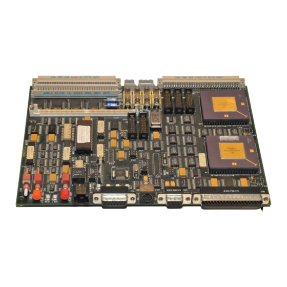
M68360QUADS-040
Motorola M68360QUADS-040 Manuals
Manuals and User Guides for Motorola M68360QUADS-040. We have
1
Motorola M68360QUADS-040 manual available for free PDF download: User Manual
Motorola M68360QUADS-040 User Manual (86 pages)
Brand:
Motorola
| Category:
Motherboard
| Size: 1.38 MB
Table of Contents
Table of Contents
2
General Information
7
Introduction
7
Related Documentation
7
Abbreviations Used in the Document
7
Specifications
7
TABLE 1-1. M68360QUADS-040 Specifications
7
Cooling Requirements
8
Features
9
Hardware Block Diagram
10
Hardware Preparation and Installation
11
Introduction
11
Unpacking Instructions
11
Hardware Preparation
11
FIGURE 2-1 M68360QUADS Location Diagram
12
ADI Port Address Selection
13
FIGURE 2-2 Configuration Dip-Switch - DSW1
13
Caches Enable / Disable
14
MMU Enable / Disable
14
Parity Error Interrupt Generation
14
Arbitration Configuration
14
EEST Configuration
14
User Selectable Options
14
Installation Instructions
14
Power Supply Connection
15
P7: +12V Power Supply Connection
15
ADI Installation
15
Host Computer to M68360QUADS-040 Connection
15
FIGURE 2-3 P6: +5V Power Connector
15
FIGURE 2-4 P6: +12V Power Connector
15
Terminal to M68360QUADS-040 RS-232 Connection
16
FIGURE 2-5 P1 - ADI Port Connector
16
FIGURE 2-6 P2 - RS-232 Serial Port Connector
16
Operating Instructions
17
Introduction
17
Controls and Indicators
17
SOFT RESET Switch SW1
17
ABORT Switch SW2
17
HARD RESET - Switches SW1 & SW2
17
EEST Configuration Jumpers J1 to J6
17
TPEN Jumper - J1
17
APORT Jumper - J2
17
TPAPCE Jumper - J3
17
TPFULDL Jumper - J5
18
LOOP - Diagnostic Loopback Jumper - J6
18
Hardware Breakpoint Usage Jumper - J7
18
Parity Error Interrupt Jumper - J8
18
Bus Request Jumper - J9
18
Bus Grant Jumper - J10
18
HALT Indicator - LD10
18
040RUN Indicator - LD8
18
DMARUN Indicator - LD9
19
Ethernet TX Indicator - LD3
19
Ethernet RX Indicator - LD2
19
Ethernet CLSN Indicator LD4
19
Ethernet LIL Indicator - LD5
19
Ethernet PLR Indicator - LD6
19
Ethernet JABB Indicator - LD1
19
POWER Indicator - LD7
19
Memory Map
19
TABLE 3-1. EC040 Cycle Types and Responding Devices
19
Main Memory Map
20
TABLE 3-2 M68360QUADS-040 Main Memory Map
20
Programming the Slave QUICC
21
Module Base Address Register
21
Module Configuration Register
21
CLKO Control Register
21
PLL Control Register
21
Port E Pin Assignment Register
21
System Protection Control
21
Global Memory Register
22
Base Register 0 and Option Register 0
22
Base Register 1 and Option Register 1
22
Base Register 2 and Option Register 2
23
Base Register 3 and Option Register 3
23
Base Register 4 and Option Register 4
23
Base Register 5 and Option Register 5
24
Base Register 6 and Option Register 6
24
Base Register 7 and Option Register 7
24
Port a Open Drain Register
24
Port a Data Register
24
Port a Data Direction Register
24
Port a Pin Assignment Register
24
Port B Open Drain Register
24
Port B Data Register
24
Port B Data Direction Register
25
Port B Pin Assignment Register
25
Port C Data Register
25
Port C Data Direction Register
25
Port C Pin Assignment Register
25
Port C Special Options Register
25
Functional Description
26
Introduction
26
Master MC68EC040
26
RESET for the 68EC040 & the QUICC
26
Utilizing the MC68EC040 Data Cache
27
Interrupts on the M68360QUADS-040
27
ABORT Push-Button
27
Host - NMI
28
Hardware-Breakpoint Interrupt
28
Parity Error Interrupt
28
Host Request / Acknowledge Interrupt
28
Bus Arbitration
28
System Utilities
29
Breakpoints Generator
29
Bus Monitor
29
FIGURE 4-1 Arbitration Scheme
29
Spurious Interrupt Monitor
30
Software Watch-Dog
30
Periodic Interval Timer - PIT
30
Clock Generator
30
Flash PROM
30
Bursting SRAM
30
Eeprom
31
Dram
31
Slave QUICC
31
DRAM Controller
32
Chip Select TA~ and DSACK~ Generator
32
ADI Port
32
TABLE 4-1. DRAM SIMM Types
32
ADI Port Signal Description
33
FIGURE 4-2 ADI Port Connector
33
RS-232 Serial Port
34
RS-232 Port Signal Description
35
M68360QUADS-040 Status Register
35
Status Register Bits Description
35
FIGURE 4-3 RS-232 Serial Port Connector
35
FIGURE 4-4 Status Register
35
Ethernet Controller
36
Ethernet AUI Ports Signal Description
36
FIGURE 4-5 Ethernet AUI Port Connector
36
Ethernet Twisted-Pair Port Signal Description
37
Serial EEPROM
37
Slave QUICC General Purpose I/O Pins
37
Slave QUICC Port a
37
FIGURE 4-6 Ethernet Twisted-Pair Port Connector
37
Slave QUICC Port B
38
TABLE 4-2 Port a Pins Description
38
Slave QUICC Port C
39
TABLE 4-3 Port B Pins Description
39
Slave QUICC Port E
40
TABLE 4-4 Port C Pins Description
40
Support Information
41
Introduction
41
Interconnect Signals
41
Connector P1 Interconnect Signals
41
TABLE 5-1 Connector P1 Interconnect Signals
41
Connector P2 Interconnect Signals
42
Connector P3 Interconnect Signals
42
TABLE 5-2 Connector P2 Interconnect Signals
42
TABLE 5-3 Connector P3 Interconnect Signals
42
Connector P4 Interconnect Signals
43
Connector P5 Interconnect Signals
43
TABLE 5-4 Connector P8 Interconnect Signals
43
TABLE 5-5 Connector P5 Interconnect Signals
43
Connector P6 Interconnect Signals
44
Connector P7 Interconnect Signals
44
Connector P8 Interconnect Signals
44
TABLE 5-6 Connector P6 Interconnect Signals
44
TABLE 5-7 Connector P7 Interconnect Signals
44
TABLE 5-8 Connector P8 Interconnect Signals
44
Connector P9 Interconnect Signals
45
TABLE 5-9 Connector P9 Interconnect Signals
45
Connector P10 Interconnect Signals
47
Connector P11 Interconnect Signals
47
M68360QUADS-040 Parts List
47
TABLE 5-10 Parts List
47
Introduction
51
IBM-PC/XT/AT to M68360QUADS-040 Interface
51
ADI Installation in IBM-PC/XT/AT
51
SUN-4 to M68360QUADS-040 Interface
52
FIGURE A-1 Physical Location of Jumper JG1 and JG2
52
FIGURE A-2 JG1 Configuration Options
52
ADI Installation in the SUN-4
53
FIGURE A-3 ADI Board for Sbus
53
Appendix B - Adi Port Handshake Description
55
Introduction
55
ADI Port Concept and Operation Description
55
Handshake Description
55
Write Cycle from Host to M68360QUADS-040
56
FIGURE B-1 Host Computer (ADI) to M68360QUADS-040 Connection
56
Write Cycle from M68360QUADS-040 to Host
57
FIGURE B-2 Host Write to M68360QUADS-040
57
M68360QUADS-040 Interrupt to the Host
58
FIGURE B-3 M68360QUADS-040 Write Cycle to Host
58
Host Interrupt to the M68360QUADS-040
59
Host Reset to the M68360QUADS-040
59
Addressing All M68360QUADS-040
59
FIGURE B-4 M68360QUADS-040 Interrupt to Host
59
Appendix C - Pals' Equations
60
U10 - Indicators Logic
60
U11 - Reset & Abort Generator
61
U12 - ADI Controller
64
U23 - Core Disable Logic
65
U32 - Bursting Sram Controller
68
Advertisement
Advertisement
Related Products
Motorola M68HC11EVBU
Motorola M68HC11EVBD
Motorola M68EVB912B32
Motorola M68HC11EVB
Motorola M68HC11EVBU/D
Motorola M68EM05P18
Motorola MVME2604-2191A
Motorola MVME2700-13X1
Motorola MVME2700-3231A
Motorola MC145192EVK
Motorola Categories
Cell Phone
Two-Way Radio
Baby Monitor
Cordless Telephone
Radio
More Motorola Manuals
Login
Sign In
OR
Sign in with Facebook
Sign in with Google
Upload manual
Upload from disk
Upload from URL